
Safari Van AWD V6-4.3L VIN W (1996)
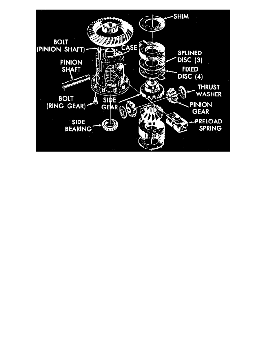
Fig. 3 Chevrolet disc type limited slip differential exploded view
1.
Remove ring gear and side bearings, then remove pinion shaft,
Fig. 3.
2.
Using a brass drift drive the preload spring from the case.
3.
Support an axle shaft in a vise, and slide the case into the shaft, then turn the case to remove both pinions and thrust washers.
4.
Remove the case from the axle shaft, then remove both side gears, clutch packs and shims. Mark the gears, clutch packs and shims for
reinstallation in same position.
5.
Inspect gears, bearings and case. Refer to
Cleaning and Inspection. See: Corporate and Eaton/7 1/2 - 8 5/8 Inch Ring Gear/Cleaning &
Inspection
6.
Inspect clutch plates and spacers, and replace if worn or overheated.
7.
Replace preload spring if force required to compress spring to height of 1 5/16 inches is not 270-330 lbs.
8.
Lubricate the clutch discs and plates with limited slip lubricant.
9.
Alternately position clutch plates and discs on a side gear, beginning and ending with a clutch plate,
Fig. 3.
10.
Position the side gear, clutch pack and original shim into the case.
11.
Install both pinion gears and thrust washers into the case, and install the pinion shaft.
12.
Install the case onto an axle shaft supported in a vise.
13.
Insert a screwdriver between the pinion shaft and the face of the side gear. Force the screwdriver in until the clutch pack is compressed.
14.
Check the backlash between the side gear and pinion gears. If backlash does not fall into the range of .005 inch to .008 inch, adjust the shim
dimension as required. Increasing shim thickness will decrease backlash; decreasing shim thickness will increase backlash. Service shims are
available from .070 inch to .122 inch in increments of .004 inch.
15.
Remove the pinion shaft, pinion gears, side gear, clutch pack and shim from the case.
16.
Install the opposite gear, clutch pack and original shim into the opposite side of the case. Place both pinion gears and thrust washers into place,
and install the pinion shaft.
17.
Follow the procedure in steps 12, 13, and 14 to determine the proper shim dimension.
18.
When proper shim dimensions have been determined, remove pinion gears and pinion shaft and install both side gears, shims and clutch packs into
case.
19.
Mount the case onto the axle shaft locked in a vise. Place both pinions and thrust washers into position 180° apart and carefully ``roll in'' by
turning the case on the shaft. A large ``C'' clamp may be used to apply slight compression against pinion gears to aid the ``rolling in'' procedure.
20.
Tap the preload spring into place with a hammer.
21.
Install the pinion shaft and lock screw.
22.
Install the side bearings and ring gear using the procedure outlined for conventional units.
23.
Place the differential unit in the carrier and adjust ring gear and pinion backlash, and gear tooth pattern.
Limited Slip