
Safari Van M V6-262 4.3L VIN W CPI (1992)
CAUTION: Fusible links cut longer than 225 mm (approx 9 in.) will not provide sufficient overload protection.
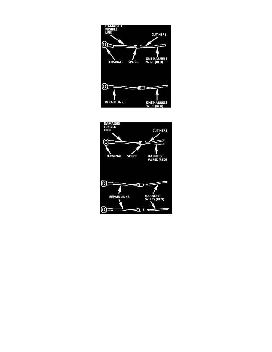
Fig. 4 Single Wire Feed Fusible Link
Fig. 5 Double Wire Feed Fusible Link
To replace a damaged fusible link, Fig. 4, cut it off beyond the splice. Replace with a repair link. When connecting the repair link, strip wire and
use staking-type pliers to crimp the splice securely in two places. For more details on splicing procedures, see Diagnostic Aids/Connector and
Wire Repair. Use Crimp and Seal splices whenever possible.
To replace a damaged fusible link which feeds two harness wires, cut them both off beyond the splice. Use two repair links, one spliced to each
harness wire, Fig. 5.
Splicing Copper Wire Using Crimp and Seal Splice Sleeves
DESCRIPTION
Crimp and Seal splice sleeves may be used on all types of insulation except tefzel and coaxial to form a one to one splice. They are to be used
where there are special requirements such as moisture scaling. (Crimp and Seal splice sleeves are included in the GM J 38125-A Terminal Repair
Kit.)
Step 1: Open the Harness
If the harness is taped, remove the tape. To avoid wire insulation damage, use a sewing "seam ripper" to cut open the harness (available from
sewing supply stores). The Crimp and Seal splice sleeves may be used on all types of insulation except tefzel and coaxial and may only be used to
form a one to one splice.
Step 2: Cut the Wire
Begin by cutting as little wire off the harness as possible. You may need the extra length of wire later if you decide to cut more wire to change the
location of a splice. You may have to adjust splice locations to make certain that each splice is at least 40 mm (1.5 in.) away from other splices,