
Savana 1/2 Ton Van V8-305 5.0L VIN M SFI (1998)
WARNING: To Reduce the Risk of Fire and Personal Injury: Before connecting the fitting, always apply a few drops of clean engine oil to
the male pipe end. This will ensure proper reconnection and prevent a possible fuel leak (During normal operation, the O-rings located in the
female connector wall swell and may prevent proper reconnection if not lubricated.
NOTE: Remember to install the new O-rings into the inlet and outlet of the fuel injector assembly, using the seal retainer tool.
1. Apply a few drops of clean engine oil to the male tube ends.
2. Connect the fuel feed and return pipes to fuel assembly.
3. Install the fuel pipe retainer and attaching nuts. Once installed, pull on both ends of each connection to make sure they are secure.
4. Install the rear fuel pipe clip retaining bolt.
Tighten
-
Tighten the rear fuel line bracket bolt to 6.O Nm (53 lb. in.).
-
Tighten the fuel pipe retainer nuts to 3.0 Nm (27 lb. in.).
5. Install the new O-ring seals on the engine fuel feed and return pipes.
6. Connect the fuel feed and return lines to the engine fuel pipes.
Tighten
-
Tighten the fuel pipe nuts to 30.O Nm (22 lb. ft).
7. Tighten the fuel filler cap.
8. Connect the negative battery cable.
9. Check for fuel leaks.
9.1.
Turn the ignition switch to the ON position for 2 seconds.
9.2.
Turn the ignition switch to the OFF position for 10 seconds.
9.3.
Again, turn the ignition switch to the ON position.
9.4.
Check for fuel leaks.
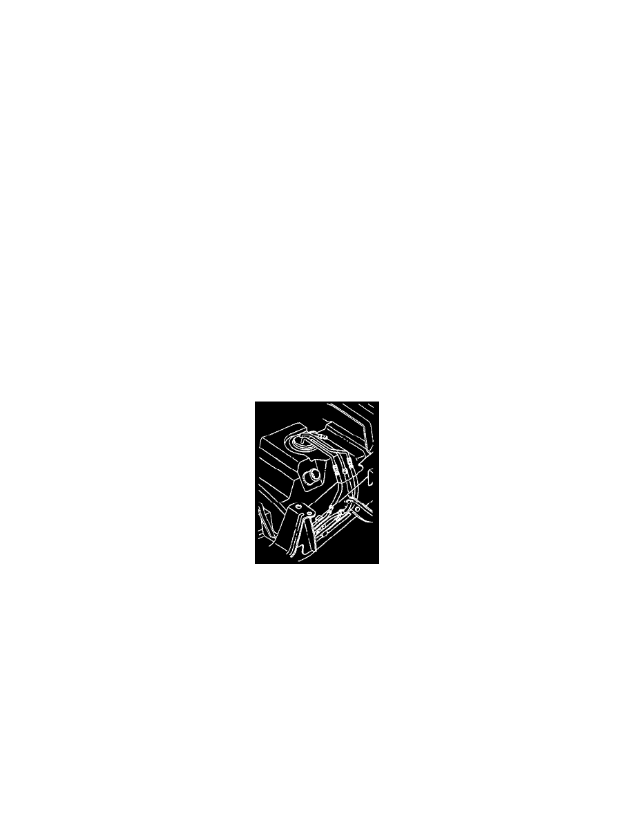
Fuel Vapor Pipes and Hoses
Diagram
REMOVAL PROCEDURE
NOTE: If the nylon pipes become kinked, and cannot be straightened, replace them.
-
Do Not attempt to repair sections of nylon pipes. If damaged, replace.
-
When replacing the vapor pipes, always replace them with original equipment or parts that meet GM specifications.
-
When replacing the vapor hoses, always replace them with original equipment or parts meeting GM specifications. Use only reinforced
fuel-resistant hose identified with the word Fluoroelastomer or GM 6163-M on the hose.
1. Remove the hardware retaining section of the pipe to be replaced. Note the location of attaching hardware for installation.
2. Remove the section of the pipe and hoses.
3. Inspect the hoses for cuts, swelling cracks and distortion. Replace as required.
4. Inspect the pipes for holes, kinks, and cracks. Replace the sections as required.
INSTALLATION PROCEDURE