
Savana 1500 RWD V6-4.3L (2007)
Information Bus: Symptom Related Diagnostic Procedures
Symptoms - Data Communications
SYMPTOMS - DATA COMMUNICATIONS
IMPORTANT: The following steps must be completed before using the symptom tables.
1. Perform the Diagnostic System Check - Vehicle before using the symptom tables in order to verify that all of the following are true:
-
There are no DTCs set.
-
The control modules can communicate via the serial data links.
2. Review the system operation in order to familiarize yourself with the system functions. Refer to:
-
Body Control System Description and Operation
-
Data Link Communications Description and Operation.
Visual/Physical Inspection
-
Inspect for aftermarket devices which could affect the operation of the systems.
-
Inspect the easily accessible or visible system components for obvious damage or conditions which could cause the symptom.
Intermittent
Faulty electrical connections or wiring may be the cause of intermittent conditions. Refer to Testing for Intermittent Conditions and Poor Connections.
See: Testing and Inspection/Component Tests and General Diagnostics
Symptom List
Refer to a symptom diagnostic procedure from the following list in order to diagnose the symptom:
-
Scan Tool Does Not Power Up
-
Scan Tool Does Not Communicate with High Speed GMLAN Device
-
Scan Tool Does Not Communicate with Class 2 Device
Scan Tool Does Not Communicate with Class 2 Device
SCAN TOOL DOES NOT COMMUNICATE WITH CLASS 2 DEVICE
DIAGNOSTIC INSTRUCTIONS
-
Perform the Diagnostic System Check - Vehicle prior to using this diagnostic procedure. See: Testing and Inspection/Initial Inspection and
Diagnostic Overview/Diagnostic System Check - Vehicle
-
Review Strategy Based Diagnosis for an overview of the diagnostic approach.
-
Diagnostic Procedure Instructions provides an overview of each diagnostic category.
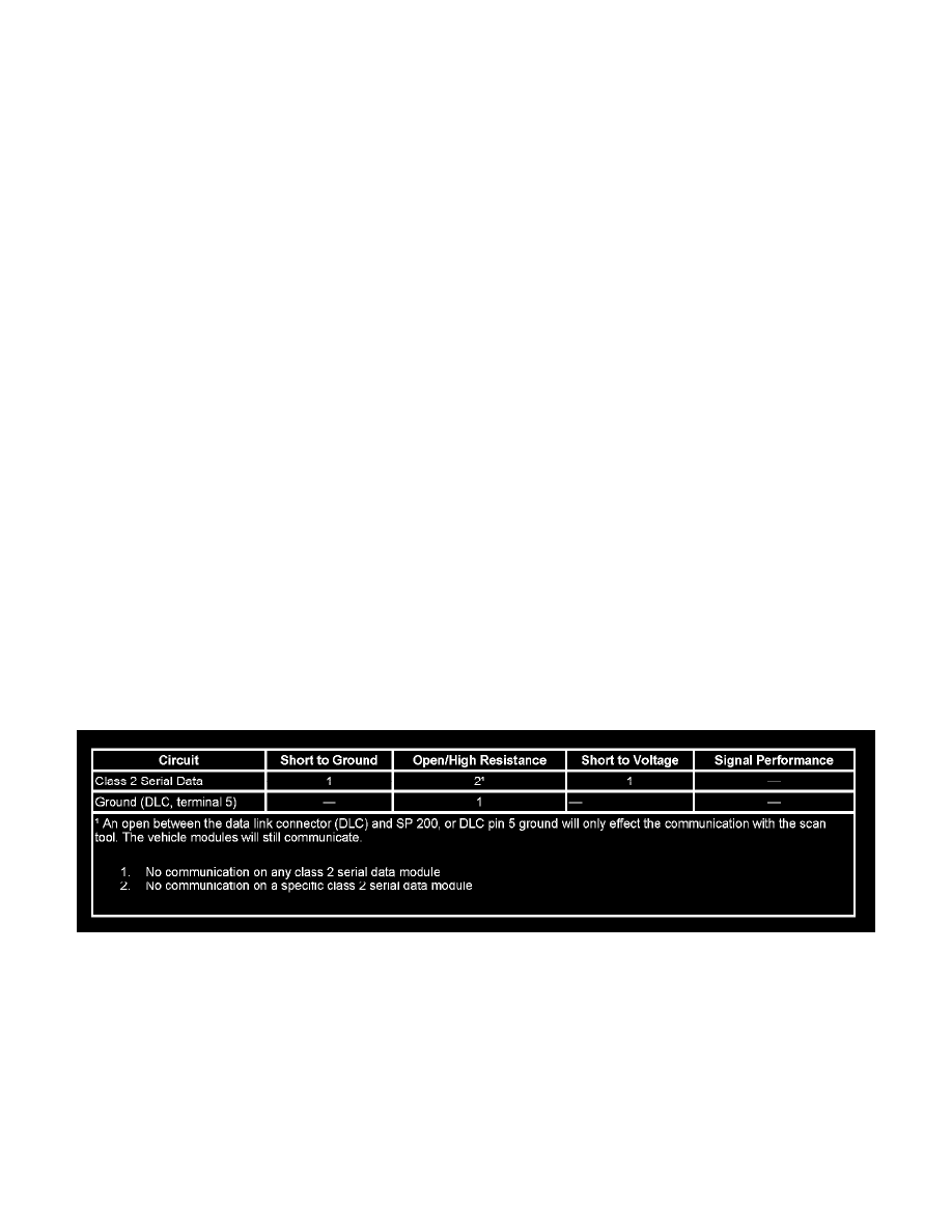
DIAGNOSTIC FAULT INFORMATION
CIRCUIT DESCRIPTION
Modules connected to the class 2 serial data circuit monitor for serial data communications during normal vehicle operation. Operating information
and commands are exchanged among the modules. Connecting a scan tool to the data link connector (DLC) allows communication with the modules
for diagnostic purposes. The class 2 serial data circuit uses SP 200 (splice pack comb) as a common connection between some modules and the DLC.
DTCs may be set due to this symptom and during this diagnostic procedure.
DIAGNOSTIC AIDS
-
Use the Data Link References to identify the class 2 serial data modules.
-
This test is used for a total class 2 communication failure. If only 1 module is not communicating and sets no DTC, ensure that the vehicle is
equipped with the module, then use DTC U1001-U1254 for diagnostics.
-
The body control module (BCM) detects that the ignition is ON and sends the appropriate power mode message to the other modules. Therefore,