
Savana 2500 V6-4.3L VIN X (2005)
throughout the vehicle. CPAs are also used in all SIR system electrical connectors. The CPA ensures that the connector halves cannot vibrate apart. You
must have the CPA in place in order to ensure good contact between the mating terminals, of the connector.
Terminal Position Assurance Locks
TERMINAL POSITION ASSURANCE LOCKS
The terminal position assurance (TPA) insert resembles the plastic combs used in the control module connectors. The TPA keeps the terminal securely
seated in the connector body. Do not remove the TPA from the connector body unless you remove a terminal for replacement.
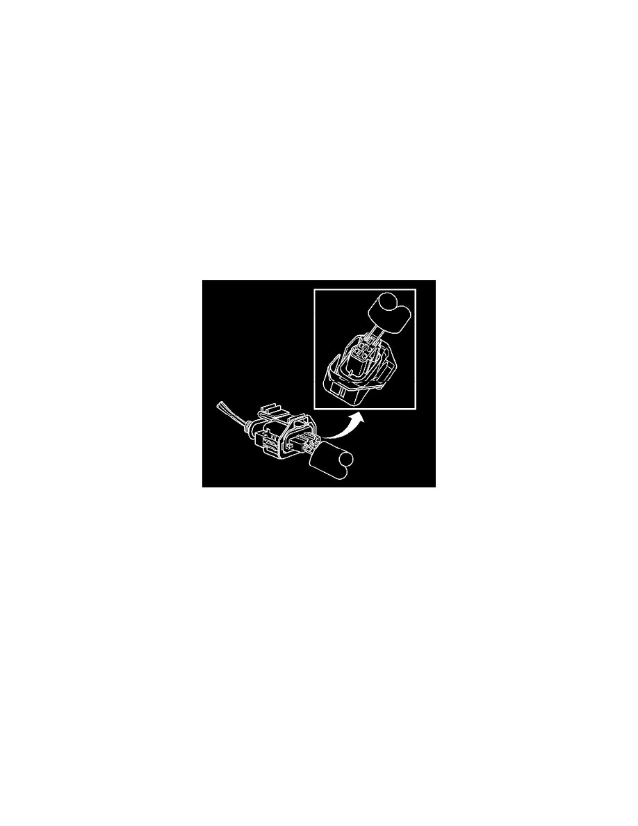
Bosch Connectors (BSK)
BOSCH CONNECTORS (BSK)
TOOLS REQUIRED
J-38125 Terminal Repair Kit
TERMINAL REMOVAL PROCEDURE
1. Disconnect the connector from the component.
2. Remove the wire dress cover, if necessary.
3. Push the wire side of the terminal that is being removed toward the connector and hold it in position.
4. Insert the J 38125-561 tool into the 2 cavities on each side of the terminal at the front of the connector and push until you feel the tool disengage
the terminal retainers. See the release tool cross reference in the Reference Guide of the J-38125 to ensure that the correct release tool is used.
5. Carefully pull the terminal out of the connector. Always remember never use force when pulling a terminal out of a connector. If the terminal is
difficult to remove, repeat the entire procedure.
TERMINAL REPAIR PROCEDURE
Use the appropriate terminal and follow the instructions in the J-38125.
Bosch Connectors (0.64)
BOSCH CONNECTORS (0.64)
TOOLS REQUIRED
J-38125 Terminal Repair Kit
TERMINAL REMOVAL PROCEDURE
1. Locate the lever lock on the wire dress cover. While pressing the lock, pull the lever over and past the lock until the lever is at the end of its travel.
2. Disconnect the connector from the component.
3. Pull the rubber boot that covers the wires back to expose the end of the connector dress cover.
4. Place the connector locking lever in the center of the connector.