
Savana 2500 V6-4.3L VIN X (2005)
IMPORTANT: On connectors with more than one terminal the service loop may not be large enough to remove the terminal and crimp on a new
one. If the terminal wire does not have a large enough service loop for removal, cut the wire 5 cm (2 in) behind the connector before removal.
TERMINAL REPAIR
1. If the wire needed to be cut in order to remove the terminal, gently push a small length of the same size wire through the back of the connector
cavity until there is enough wire exposed in order to crimp on a new terminal. If the wire was not cut, cut the existing wire as close to the old
terminal as possible.
2. Strip 5 mm (3/16 in) of insulation from the wire.
3. Crimp a new terminal to the wire.
4. Solder the crimp with rosin core solder.
TERMINAL INSTALLATION
1. Align the terminal and pull the wire from the back of the connector in order to seat the terminal.
2. If necessary, cut the new wire to proper length and splice with existing circuit. Refer to Splicing Copper Wire Using Splice Sleeves.
3. If the connector is outside of the passenger compartment, apply dielectric grease to the connector.
4. Install the TPA, CPA, and/or the secondary locks.
Delphi Connectors (Micro-Pack 100W)
DELPHI CONNECTORS (MICRO-PACK 100W)
TOOLS REQUIRED
J-38125 Terminal Repair Kit
TERMINAL REMOVAL PROCEDURE
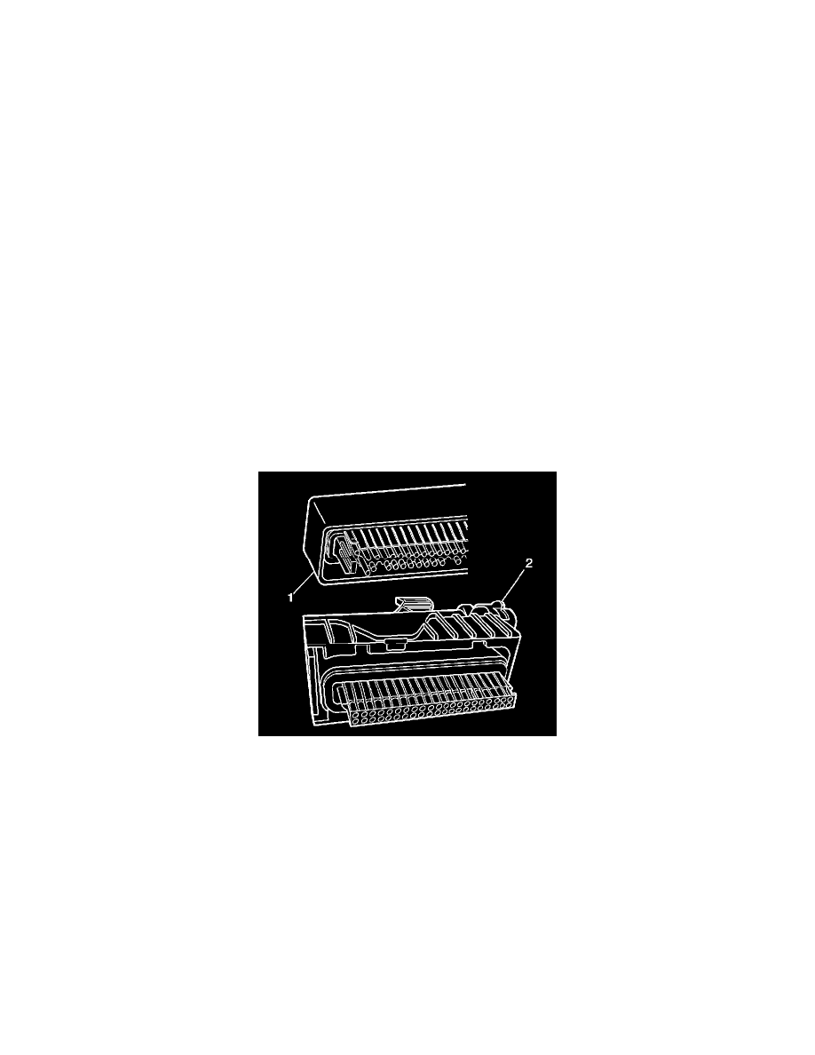
There are 2 styles of Micro-Pack 100W connectors. These connectors are very similar but use different terminals and have some minor physical
differences also.
The first connector design of the Micro-Pack 100W (1) has a white connector interface that holds the terminals. The second design of the Micro-Pack
100W (2) has a gray interface to hold the terminals. Also, the first design has terminal cavities that are further apart (3 mm centerline) and offset from
the other row of terminal cavities in the connector. The second design has terminals cavities that are closer together (2.54 mm centerline) and aligned
vertically. One other way to identify the second design is the thin strip of material that runs along the outside of the cavities.
IMPORTANT: There are 2 styles of Micro-Pack 100W terminals which are very similar. Ensure that you have the correct terminal before crimping
the new terminal to the wire. The first design connector uses the longer terminal (1) that has a raised area in front of the recess in the terminal. The
second design connector uses the shorter terminal without the raised area.