
Savana 2500 V6-4.3L VIN X (2005)
4. Insert the terminal into the crimp tool until the core wings are flush with the anvil on the crimp tool. Be sure that the wings are pointed toward the
crimp tool former and release the spring locator. The locator will hold the terminal in place. Inspect the alignment of the terminal wings with the
crimp tool former. If the terminal wings are wider than the crimp tool former, remove the terminal and bend the terminal wings in slightly.
5. Place stripped wire into terminal.
6. Crimp the new terminal to the wire. If a jam occurs, press the emergency release to open applicator.
TERMINAL REPLACEMENT PROCEDURE
After the terminal is crimped to the wire perform the following procedure in order to replace Micro-Pack 100 terminals.
1. Slide the new terminal into the correct cavity at the back of the connector.
2. Push the terminal into the connector until it locks into place. The new terminal should be even with the other terminals. Ensure that the terminal is
locked in place by gently pulling on the wire.
3. To assemble the connector, reverse the Terminal Removal Procedure.
Delphi Connectors (Micro .64)
DELPHI CONNECTORS (MICRO.64)
TOOLS REQUIRED
J-38125 Terminal Repair Kit
REMOVAL PROCEDURE
Follow the steps below in order to remove terminals from Micro 64 connectors.
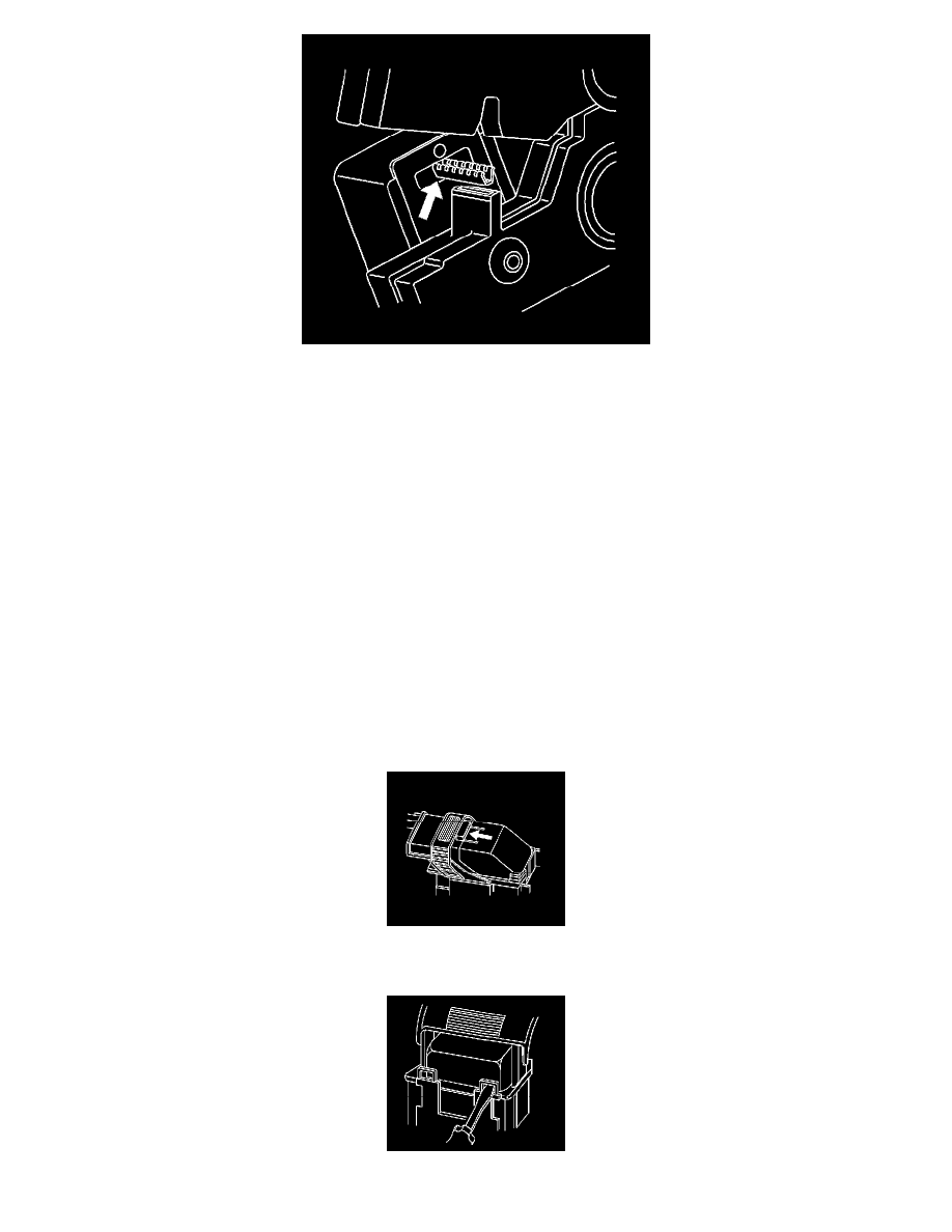
1. Locate the lever lock on the wire dress cover. While depressing the lock, pull the lever over and past the lock.
2. Disconnect the connector from the component.
3. Locate the dress cover locking tabs at the front of the connector. Using a small flat-blade tool push down on one of the locking tabs and pull the