
Savana 2500 V6-4.3L VIN X (2005)
Global Positioning System Module: Service and Repair
Communication Interface Module Replacement
COMMUNICATION INTERFACE MODULE REPLACEMENT
REMOVAL PROCEDURE
1. Remove the drivers knee bolster.
IMPORTANT: The vehicle communication interface module (VCIM) has a specific set of unique numbers that tie the module to each vehicle. These
numbers, the 10-digit station identification and the 11-digit electronic serial number, are used by the National Cellular Network and OnStar(R) to
identify the specific vehicle. Because these numbers are tied to the vehicle identification number of the vehicle, you must never exchange these parts
with those of another vehicle.
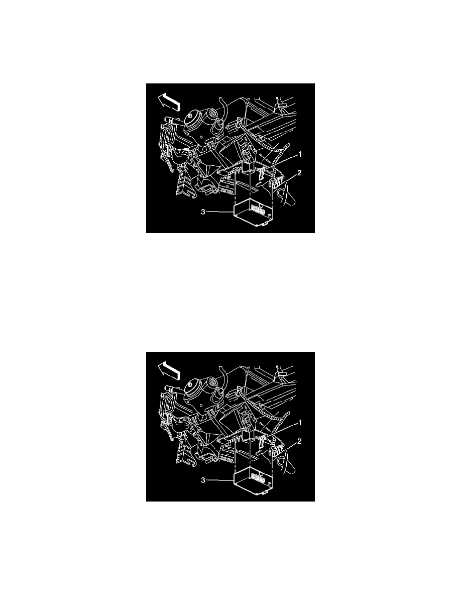
2. Disconnect the electrical connectors and the coaxial cable (2) from the module.
3. Release the communication interface module retaining tab (1).
4. Remove the communication interface module (3) from the module bracket.
INSTALLATION PROCEDURE
1. When replacing a VCIM, record the 11-digit electronic serial number (ESN) and the 10-digit station identification (STID) number from the label
on the new VCIM.
2. Slide the communication interface module (3) into the bracket.
3. Push in on the module (3) at the retaining tab (2) until an audible click is heard indicating the module is secured to the bracket.
4. Connect the electrical connectors and the coaxial cable (2) to the communication interface module (3).
5. Reconfigure the OnStar(R) system. Refer to OnStar Reconfiguration (Gen 6) OnStar Reconfiguration (Gen 6.1). See: Testing and
Inspection/Programming and Relearning