
Savana 2500 V8-6.0L VIN U (2006)
Brake Rotor/Disc: Testing and Inspection
Brake Rotor Assembled Lateral Runout Measurement
Brake Rotor Assembled Lateral Runout (LRO) Measurement
^
Tools Required
-
J 39544-KIT Torque-Limiting Socket Set, or equivalent
-
J 41013 Rotor Resurfacing Kit
-
J 42450-A Wheel Hub Resurfacing Kit
-
J 45101 Hub and Wheel Runout Gage
-
J 45101-100 Conical Brake Rotor Washers
Caution: Refer to Brake Dust Caution in Service Precautions.
Important:
^
Brake rotor assembled lateral runout (LRO) exceeding the maximum allowable specification can cause thickness variation to develop in the brake
rotor over time, usually between 4,800-11,300 km (3,000-7,000 mi).
^
Brake rotor thickness variation MUST be checked BEFORE checking for assembled lateral runout (LRO). Thickness variation exceeding the
maximum acceptable level can cause brake pulsation.
1. Matchmark the position of the brake rotor to the wheel studs if this has not been done already.
2. Important:
Whenever the brake rotor has been separated from the hub/axle flange, any rust or contaminants should be cleaned from the hub/axle flange and
the brake rotor mating surfaces. Failure to do this may result in excessive assembled lateral runout (LRO) of the brake rotor, which could lead to
brake pulsation.
Inspect the mating surface of the hub/axle flange and the brake rotor to ensure that there are no foreign particles, corrosion, rust, or debris
remaining. If the wheel hub/axle flange and/or if the brake rotor mating surfaces exhibit these conditions, perform the following steps:
1. Remove the brake rotor from the vehicle.
2. Using the J 42450-A , thoroughly clean any rust or corrosion from the mating surface of the hub/axle flange.
3. Using the J 41013 , thoroughly clean any rust or corrosion from the mating surface of the brake rotor.
4. Clean the friction surfaces of the brake rotor with denatured alcohol, or an equivalent approved brake cleaner.
3. Install the rotor to the hub/axle flange using the matchmark made prior to removal.
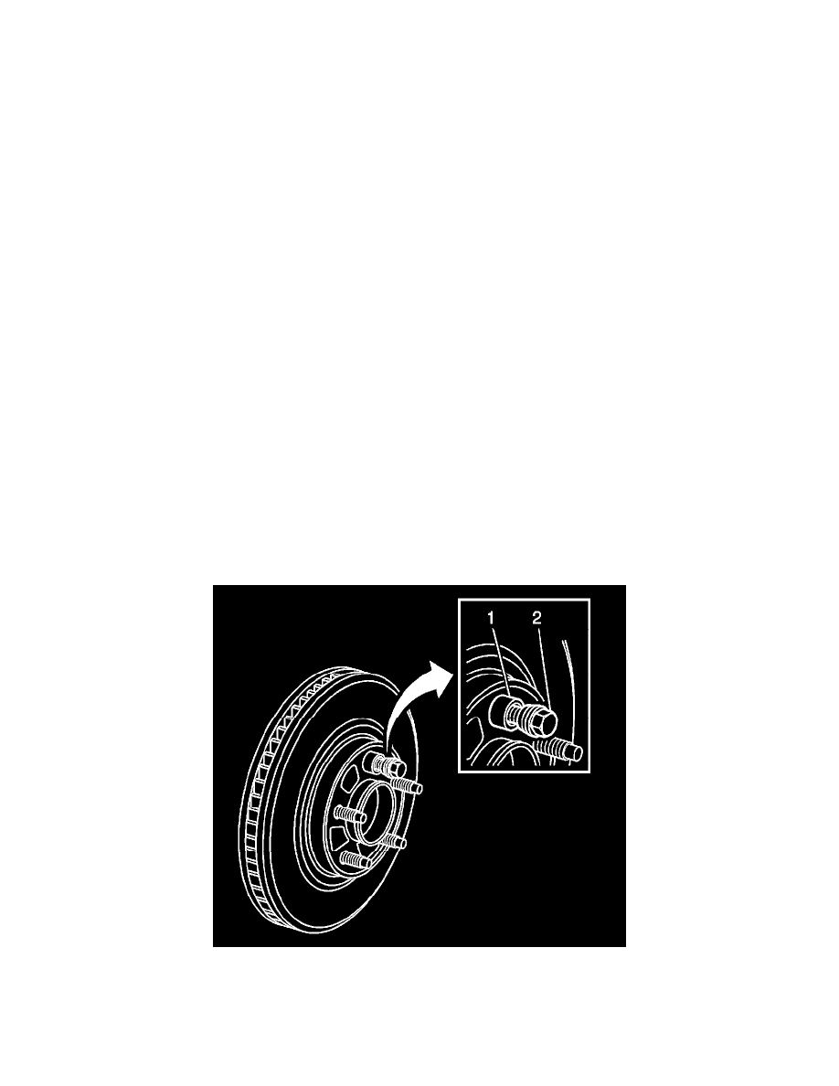
4. Hold the rotor firmly in place against the hub/axle flange and install one of the J 45101-100 (1), and one lug nut (2) onto the upper-most wheel
stud.
5. Continue to hold the rotor secure and tighten the lug nut firmly by hand.