
Savana 2500 V8-6.0L VIN U (2006)
1. Pull out the slider on the connector position assurance (CPA) until it is at the end of its travel.
2. Disconnect the connector from the component.
3. Remove the wire dress cover, if necessary.
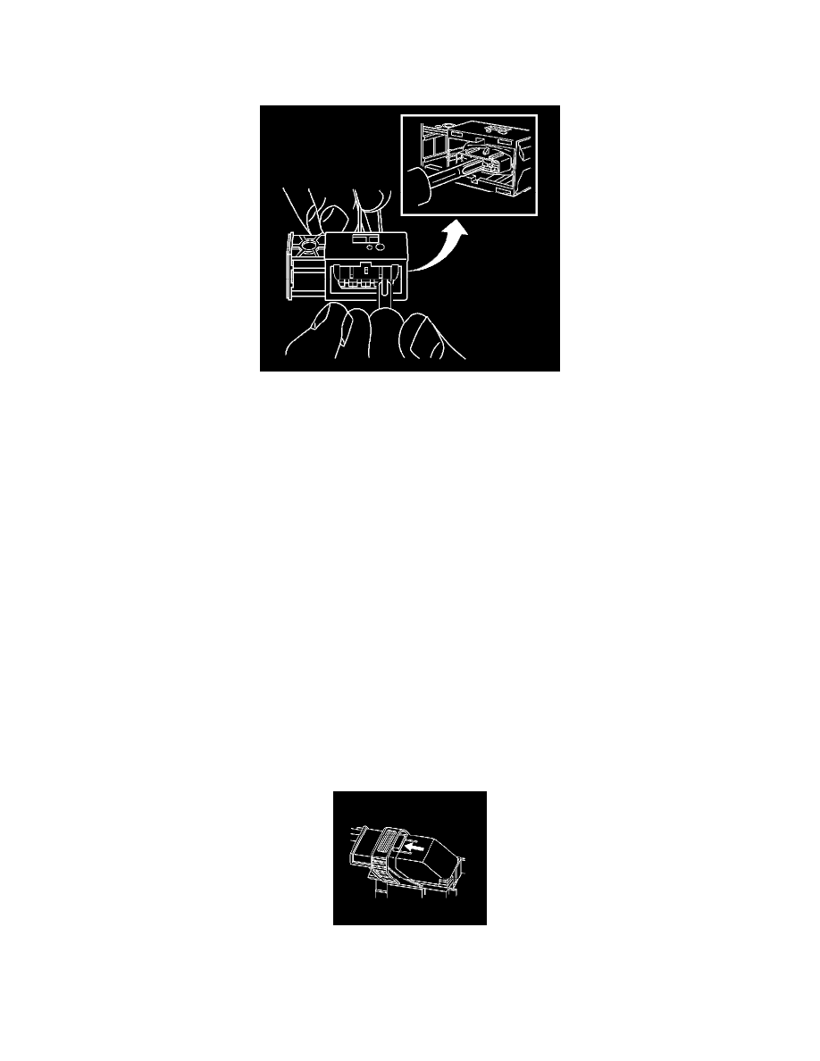
4. Push the wire side of the terminal that is being removed toward the connector and hold it in position.
5. Insert the J 38125-557 (GM P/N 12122378) into the 2 cavities on each side of the terminal at the front of the connector and push until you feel the
tool disengage the terminal retainers. See the release tool cross reference in the Reference Guide of the J-38125 to ensure that the correct release
tool is used.
6. Carefully pull the terminal out of the connector. Always remember never use force when pulling a terminal out of a connector. If the terminal is
difficult to remove, repeat the entire procedure.
TERMINAL REPAIR PROCEDURE
Use the appropriate terminal and follow the instructions in the J-38125.
Connector Position Assurance Locks
TERMINAL POSITION ASSURANCE LOCKS
The terminal position assurance (TPA) insert resembles the plastic combs used in the control module connectors. The TPA keeps the terminal securely
seated in the connector body. Do not remove the TPA from the connector body unless you remove a terminal for replacement.
Delphi Connectors (Micro .64)
DELPHI CONNECTORS (MICRO.64)
TOOLS REQUIRED
J-38125 Terminal Repair Kit
REMOVAL PROCEDURE
Follow the steps below in order to remove terminals from Micro 64 connectors.
1. Locate the lever lock on the wire dress cover. While depressing the lock, pull the lever over and past the lock.
2. Disconnect the connector from the component.