
Savana 2500 2WD V6-4.3L VIN X (2004)
NOTE: Refer to Test Probe Notice in Service Precautions.
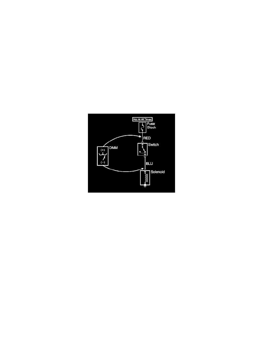
The following procedure measures the voltage at a selected point in a circuit.
1. Disconnect the electrical harness connector for the circuit being tested, if necessary.
2. Enable the circuit and/or system being tested. Use the following methods:
-
Turn ON the ignition, with the engine OFF.
-
Turn ON the engine.
-
Turn ON the circuit and/or system with a scan tool in Output Controls.
-
Turn ON the switch for the circuit and/or system being tested.
3. Select the V (AC) or V (DC) position on the DMM.
4. Connect the positive lead of the DMM to the point of the circuit to be tested.
5. Connect the negative lead of the DMM to a good ground.
6. The DMM displays the voltage measured at that point.
Measuring Voltage Drop
MEASURING VOLTAGE DROP
NOTE: Refer to Test Probe Notice in Service Precautions.
The following procedure determines the difference in voltage potential between 2 points.
1. Set the rotary dial of the DMM to the V (DC) position.
2. Connect the positive lead of the DMM to 1 point of the circuit to be tested.
3. Connect the negative lead of the DMM to the other point of the circuit.
4. Operate the circuit.
5. The DMM displays the difference in voltage between the 2 points.
Probing Electrical Connectors
PROBING ELECTRICAL CONNECTORS
IMPORTANT: Always be sure to reinstall the connector position assurance (CPA) and terminal position assurance (TPA) when reconnecting
connectors or replacing terminals.
Frontprobe
Disconnect the connector and probe the terminals from the mating side (front) of the connector.
NOTE: Do not insert test equipment probes into any connector or fuse block terminal. The diameter of the test probes will deform most terminals. A
deformed terminal can cause a poor connection, which can result in system failures. Always use the J 35616- B Connector Test Adapter Kit or the J
42675 Flat Wire Probe Adapter Kit in order to frontprobe terminals. Do not use paper clips or other substitutes as they can damage terminals and
cause incorrect measurements.