
Savana 3/4 Ton Van V6-4.3L VIN W (1998)
Diagnostic Chart
3. Remove the spring retainers (1) off the edges of the VCM.
4. Slide the VCM out of the bracket at an angle.
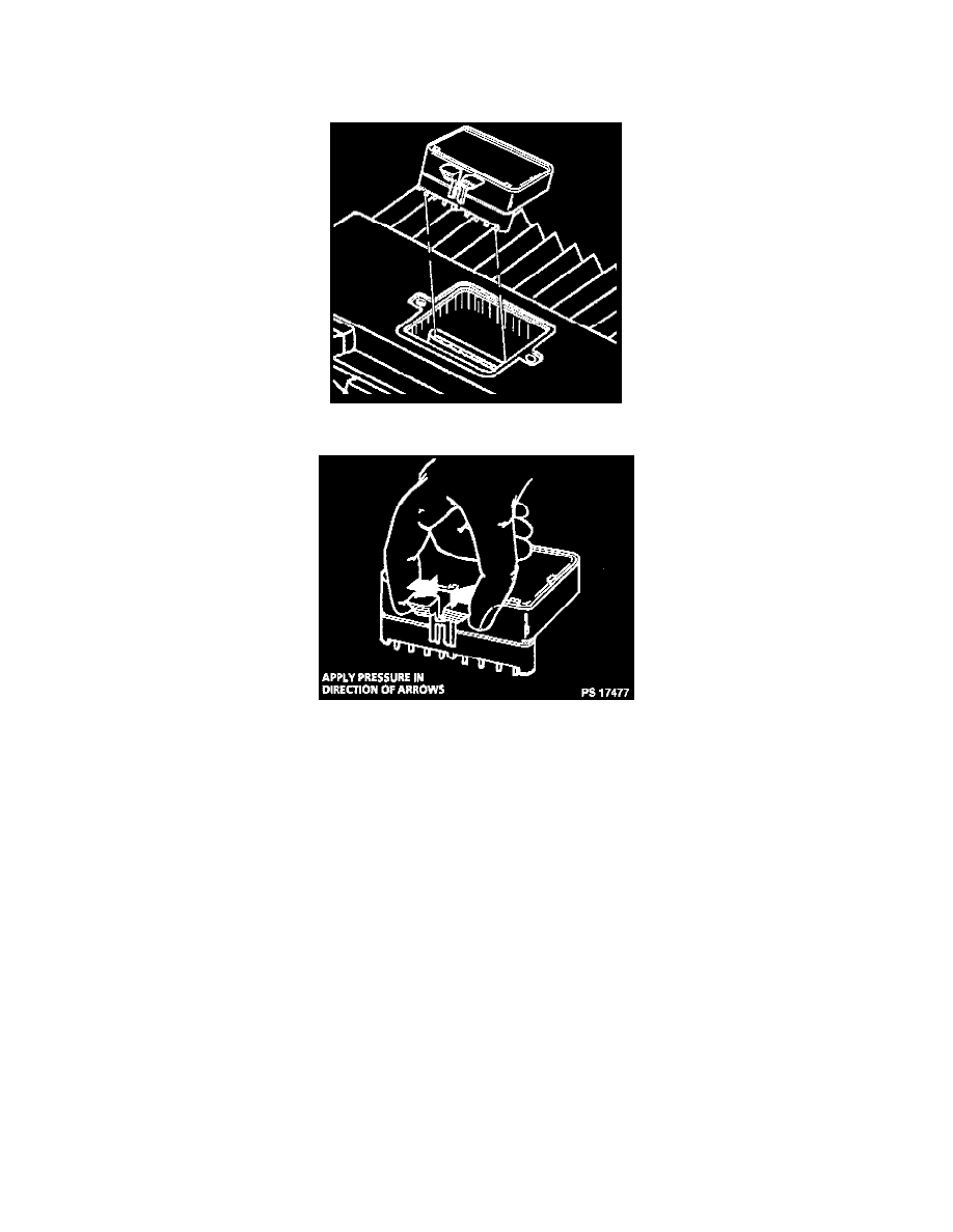
5. Remove the PROM / Electronic Spark Control Module access cover.
Removing Knock Sensor Module From PCM
6. Remove the PROM / Electronic Spark Control Module by gently squeezing the PROM locks together.
INSTALLATION PROCEDURE
IMPORTANT: Press only on the ends of the PROM I Electronic Spark Control Module. Gently press on the PROM until it is firmly seated in the
socket. Listen for the click.
NOTICE: In order to prevent possible electrostatic discharge (ESD) damage to the VCM, do not touch the connector pins or soldered components on
the circuit board.
1. Align the notches of the PROM / Electronic Spark Control Module with the notches in the PROM socket.
2. Install the PROM in the PROM socket.
3. Install the access cover on the VCM.
4. Install the VCM in the engine compartment.
5. Install the retaining springs (1) over the edges of the VCM.
6. Install the connectors to the VCM.
7. The MIL, antilock and brake lamps will continue to be enabled until the VCM is programmed. Once the programming is complete, the lamps will
turn off and normal operation will occur.
8. Connect the negative battery cable.
9. Proceed to the VCM programming.
VCM PROGRAMMING
NOTE: VCM programming must be performed by the vehicle dealership.