
Savana 3500 V8-4.8L (2009)
4. Solder the crimp with rosin core solder.
Terminal Installation
1. Align the terminal and pull the wire from the back of the connector in order to seat the terminal.
2. If necessary, cut the new wire to proper length and splice with existing circuit. Refer to Splicing Copper Wire Using Splice Sleeves (See: Testing
and Inspection/Component Tests and General Diagnostics).
3. If the connector is outside of the passenger compartment, apply dielectric grease to the connector.
4. Install the TPA, CPA, and/or the secondary locks.
Delphi Connectors (Push To Seat)
Delphi Connectors (Push To Seat)
Tools Required
J-38125 Terminal Repair Kit
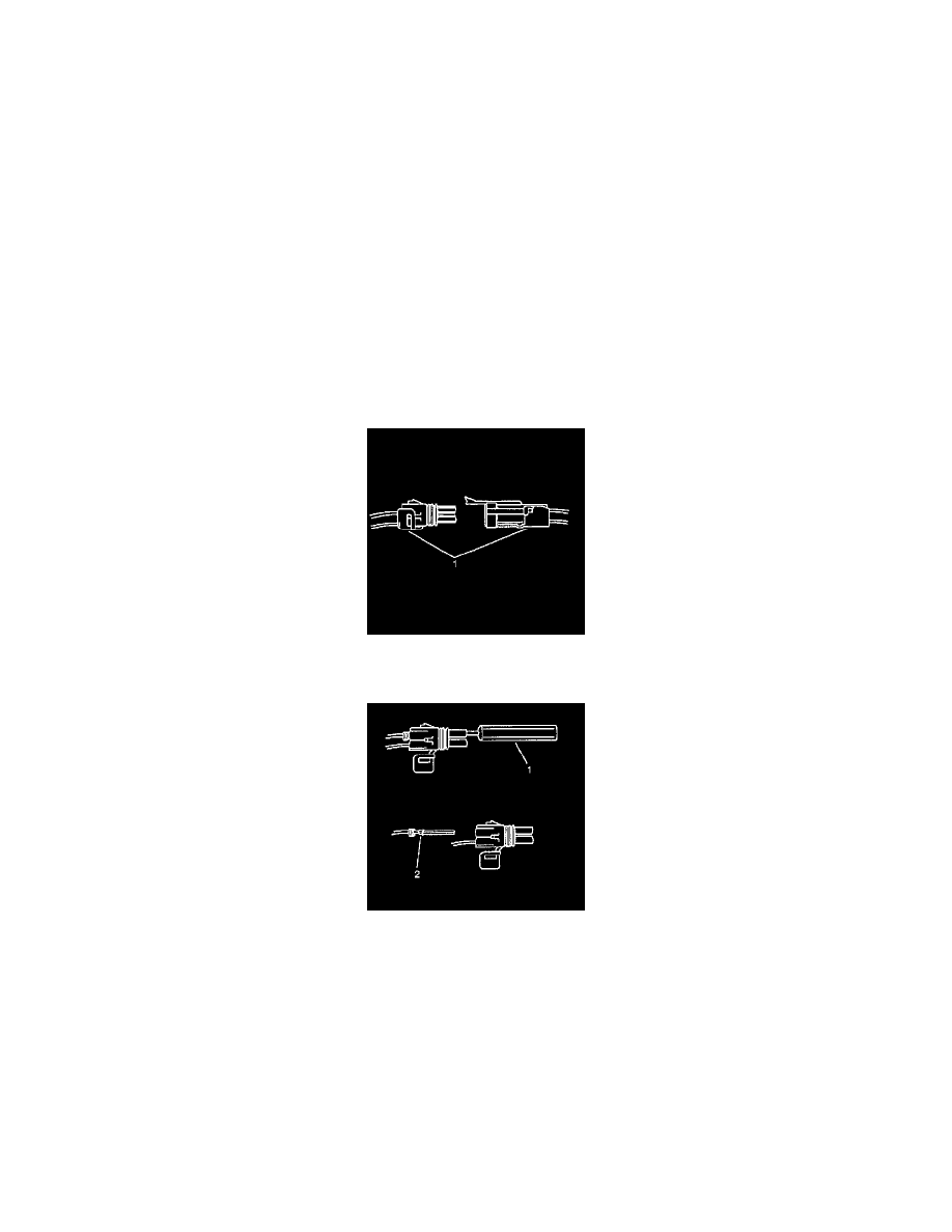
Terminal Removal
Follow the steps below in order to repair push to seat connectors.
1. Remove the terminal position assurance (TPA) device, the connector position assurance (CPA) device, and/or the secondary lock.
2. Separate the connector halves (1).
3. Use the proper pick or removal tool (1) in order to release the terminal. See the release tool cross reference in the Reference Guide of the J-38125
to ensure that the correct release tool is used.
4. Gently pull the cable and the terminal (2) out of the back of the connector.