
Savana 4500 V8-6.6L DSL Turbo (2009)
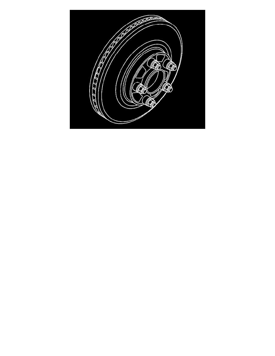
6. Install the remaining J-45101-100 - washers and lug nuts onto the wheel studs and tighten the nuts firmly by hand in a star-pattern.
7. Using the J-39544-KIT - set , or equivalent, tighten the lug nuts in a star-pattern to specification, in order to properly secure the rotor. Refer to
Tire and Wheel Removal and Installation (See: Maintenance/Wheels and Tires/Service and Repair).
8. Measure the assembled LRO of the brake rotor. Refer to Brake Rotor Assembled Lateral Runout Measurement (See: Brake Rotor Assembled
Lateral Runout Measurement).
9. Compare the amount of change between this measurement and the original measurement.
10. If this measurement is within specifications, proceed to step 14.
11. If this measurement still exceeds specifications, repeat steps 1-9 until the best assembled LRO measurement is obtained.
12. Matchmark the final location of the rotor to the wheel studs if the orientation is different than it was originally.
13. If the brake rotor assembled LRO measurement still exceeds the maximum allowable specification, refer to Brake Rotor Assembled Lateral
Runout Correction (See: Brake Rotor Assembled Lateral Runout Correction).
14. If the brake rotor assembled LRO is within specification, install the brake caliper and depress the brake pedal several times to secure the rotor in
place before removing the J-45101-100 - washers and the lug nuts.