
Savana 4500 V8-6.6L DSL Turbo (2009)
5. Compare the thickness variation recorded to the following specification:
Brake rotor maximum allowable thickness variation 0.025 mm (0.001 in).
6. If the brake rotor thickness variation exceeds the specification, the rotor requires refinishing or replacement.
7. Using the micrometer measure and record any grooves present on the rotor braking surface.
8. Compare the groove/scoring depth recorded to the following specification:
Brake rotor maximum allowable scoring 1.50 mm (0.059 in).
9. If the brake rotor scoring depth exceeds the specification, or if an excessive amount of scoring is present, the rotor requires refinishing or
replacement.
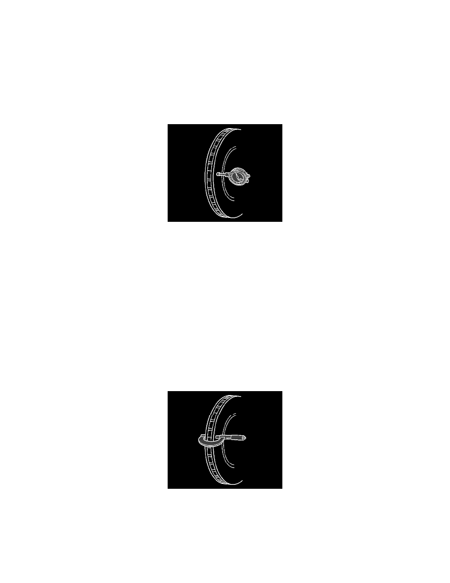
10. Mount a dial indicator J 8001 or equivalent, and position the indicator button so it contacts the brake rotor at a 90 degree angle, approximately 13
mm (0.5 in) from the rotor's outer edge.
11. Measure and record the lateral runout of the brake rotor.
1. Rotate the rotor until the lowest reading is displayed on the indicator dial and zero the dial.
2. Rotate the rotor until the highest reading is displayed on the dial.
3. Measure and record the amount of lateral runout.
12. Compare the lateral runout of the brake rotor to the following specification:
Brake rotor maximum allowable lateral runout 0.05 mm (0.002 in).
13. If the brake rotor lateral runout exceeds the specification the rotor requires refinishing or replacement.
Brake Rotor Thickness Measurement
Brake Rotor Thickness Measurement
Warning: Refer to Brake Dust Warning (See: Service Precautions/Technician Safety Information/Brake Dust Warning).
1. Clean the brake pad lining contact surface of the brake rotor with denatured alcohol or an equivalent brake cleaner.
2. Using a calibrated micrometer measure and record the lowest thickness of the brake rotor at 4 or more points equally spaced around the rotor.
Ensure that the measurements are only taken within the brake pad lining contact area and that the micrometer is positioned the same distance from
the outside edge of the rotor for each measurement.
3. Compare the lowest thickness measurement recorded to the following specifications:
-
Brake rotor minimum allowable thickness after refinishing 28.0 mm (1.102 in)
-
Brake rotor discard thickness 27.50 mm (1.083 in)