
Savana 4500 V8-6.6L DSL Turbo (2009)
Circuit/System Description
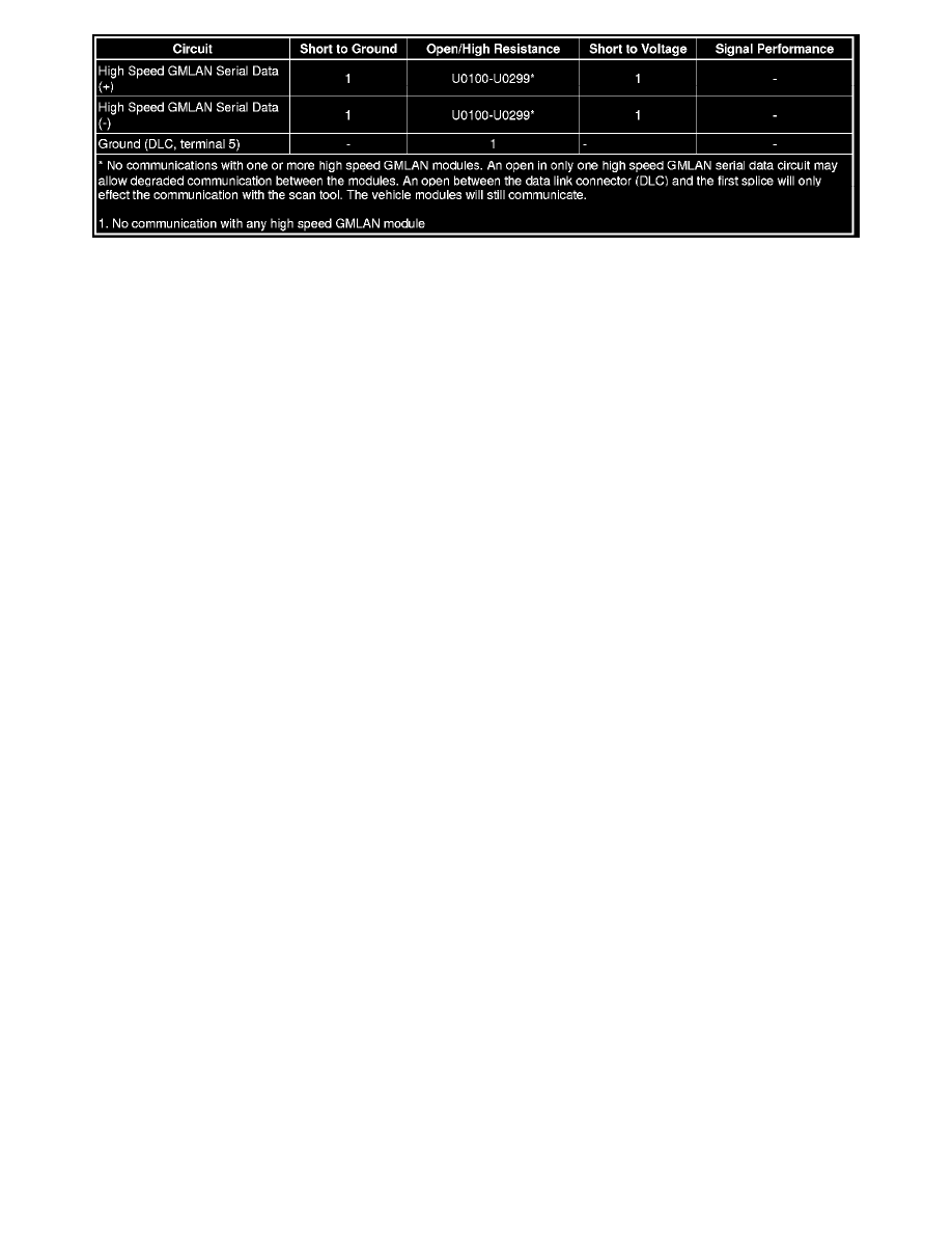
The serial data is transmitted on two twisted wires that allow speeds up to 500 Kb/s. The twisted pair is terminated with two 120 ohms resistors, one is
internal to the engine control module (ECM) and the other can be a separate resistor in a connector assembly or in another control module. The resistors
are used as the load for the High Speed GMLAN buss during normal vehicle operation. The high speed GMLAN is a differential bus. The high speed
GMLAN serial data bus (+) and high speed GMLAN serial data (-) are driven to opposite extremes from a rest or idle level of approximately 2.5 V.
Driving the lines to their extremes, adds one volt to the high speed GMLAN serial data bus (+) circuit and subtracts one volt from the high speed
GMLAN serial data bus (-) circuit. If serial data is lost, control modules will set a no communication code against the non-communicating control
module. Note that a loss of serial data DTC does not represent a failure of the module that set it.
Diagnostic Aids
*
Sometimes, while diagnosing a specific customer concern or after a repair, you may notice a history U-code present. However, there is no
associated "current" or "active" status. Loss-of- communication U-codes such as these can set for a variety of reasons. Many times, they're
transparent to the vehicle operator and technician, and/or have no associated symptoms. Eventually, they will erase themselves automatically after
a number of fault-free ignition cycles. This condition would most likely be attributed to one of these scenarios:
-
A control module on the data communication circuit was disconnected while the communication circuit is awake.
-
Power to one or more modules was interrupted during diagnosis
-
A low battery condition was present, so some control modules stop communicating when battery voltage drops below a certain threshold.
-
Battery power was restored to the vehicle and control modules on the communication circuit did not all re-initialize at the same time.
-
If a loss-of-communication U-code appears in history for no apparent reason, it is most likely associated with one of the scenarios above.
These are all temporary conditions and should never be interpreted as an intermittent fault, causing you to replace a part.
*
Do not replace a control module reporting a U code. The U code identifies which control module needs to be diagnosed for a communication
issue.
*
Communication may be available between the BCM and the scan tool with the high speed GMLAN serial data system inoperative. This condition
is due to the BCM using both the high and low speed GMLAN systems.
*
An open in the DLC ground circuit terminal 5 will allow the scan tool to operate but not communicate with the vehicle. When the scan tool
attempts to communicate with the vehicle a message "no CANdi module detected" will be displayed.
*
The engine will not start when there is a total malfunction of the high speed GMLAN serial data bus.
*
Technicians may find various Local Area Network (LAN) communication Diagnostic Trouble Codes (DTC) and no low speed GMLAN
communications with the scan tool.
*
The engine will not start when there is a total malfunction of the high speed GMLAN serial data bus.
These conditions may be caused by the installation of an aftermarket navigation radio module (see bulletins). Some customers may comment of
one or more of the following concerns:
-
Vehicle will not crank.
-
Vehicle cranks but will not start.
-
Vehicle stability enhancement system warning lights and messages.
-
PRNDL gear indicator position errors.
-
Tire Pressure Monitor (TPM) system warning lights.
Reference Information
Schematic Reference
*
Data Communication Schematics (See: Diagrams/Electrical Diagrams)
*
Control Module References (See: Testing and Inspection/Programming and Relearning)
Connector End View Reference
Component Connector End Views (See: Diagrams/Connector Views)
Description and Operation