
Savana 4500 V8-6.6L DSL Turbo (2009)
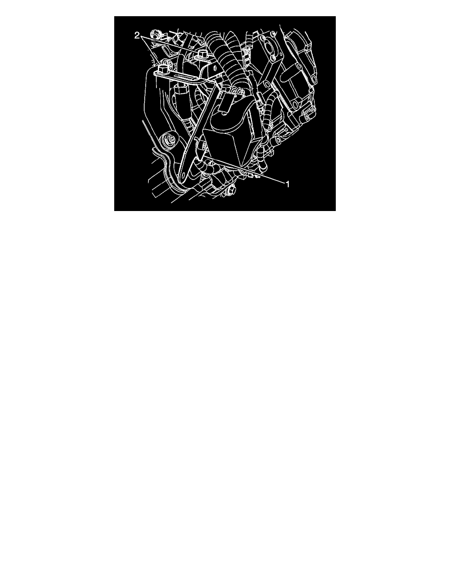
10. Position the engine wiring harness bracket (1), install the engine wiring harness to bracket bolt and the 2 engine wiring harness bracket to upper
valve cover bolts and tighten to 21 Nm (15 lb ft).
11. Connect the left engine wiring main harness connector.
12. Install the injector/glow plug wire harness retaining bolt at the lower part of the upper valve cover.
13. Install the glow plug module and bracket. Refer to Glow Plug Control Module Replacement (See: Glow Plug System/Glow Plug Control
Module/Service and Repair).
14. If equipped, install the auxiliary generator. Refer to Auxiliary Generator Replacement (See: Starting and Charging/Charging
System/Alternator/Service and Repair/Auxiliary Generator Replacement).
15. Install the upper fan shroud. Refer to Engine Coolant Fan Upper Shroud Replacement (4.3L, 4.8L, 5.3L, 6.0L, 6.2L, 7.0L) (See: Engine, Cooling
and Exhaust/Cooling System/Fan Shroud/Service and Repair)Engine Coolant Fan Upper Shroud Replacement (6.6L) (See: Engine, Cooling and
Exhaust/Cooling System/Fan Shroud/Service and Repair).
16. If the fuel injectors were replaced, refer to Fuel Injector Flow Rate Programming (See: Procedures).
17. Prime the fuel system. Refer to Fuel System Priming (See: Service and Repair/Fuel System Priming).
18. Start the engine. If the engine stalls, repeat the above step.
19. Once the engine starts, inspect for fuel leaks.
Fuel Injector Replacement (Right)
Fuel Injector Replacement (Right)
Special Tools
*
EN-47909 Injector Bore and Sleeve Cleaning Kit
*
J-46594 Fuel Injector Puller
Removal Procedure