
Savana 4500 V8-6.6L DSL Turbo (2009)
High Idle Switch: Testing and Inspection
High Idle Switch Diagnosis
Diagnostic Instructions
*
Perform the Diagnostic System Check - Vehicle (See: Testing and Inspection/Initial Inspection and Diagnostic Overview/Diagnostic System
Check - Vehicle) prior to using this diagnostic procedure.
*
Review Strategy Based Diagnosis (See: Testing and Inspection/Initial Inspection and Diagnostic Overview/Strategy Based Diagnosis) for an
overview of the diagnostic approach.
*
Diagnostic Procedure Instructions (See: Testing and Inspection/Initial Inspection and Diagnostic Overview/Diagnostic Procedure Instructions
)provide an overview of each diagnostic category.
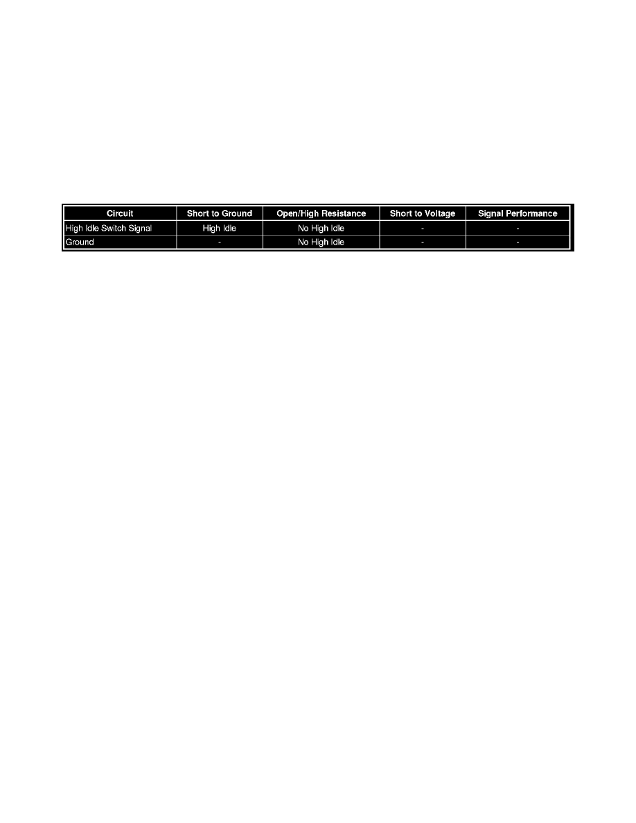
Diagnostic Fault Information
Reference Information
Schematic Reference
Engine Controls Schematics (See: Diagrams/Electrical Diagrams)
Connector End View Reference
Component Connector End Views (See: Diagrams/Connector Views)
Electrical Information Reference
*
Circuit Testing (See: Testing and Inspection/Component Tests and General Diagnostics)
*
Connector Repairs (See: Testing and Inspection/Component Tests and General Diagnostics)
*
Testing for Intermittent Conditions and Poor Connections (See: Testing and Inspection/Component Tests and General Diagnostics)
*
Wiring Repairs (See: Testing and Inspection/Component Tests and General Diagnostics)
Scan Tool Reference
Control Module References (See: Testing and Inspection/Programming and Relearning)for scan tool information
Circuit/System Verification
Ignition ON, observe the scan tool High Idle switch parameter while exercising the switch. The reading should change between ON/OFF.
Circuit/System Testing
1. Ignition OFF, disconnect the harness connector at the high idle switch.
2. Test for less than 5 ohms between the ground circuit terminal A and ground.
‹› If greater than 5 ohms, test the ground circuit for an open/high resistance.
3. Ignition ON, verify the scan tool High Idle switch parameter is OFF.
‹› If not OFF, test the signal circuit for a short to ground. If the circuit tests normal, replace the ECM.
4. Install a 3A fused jumper wire between the signal circuit terminal C and ground. Verify the scan tool High Idle switch parameter is ON.
‹› If not ON, test the signal circuit for a short to voltage or an open/high resistance. If the circuit tests normal, replace the ECM.
5. If all circuits test normal, test or replace the high idle switch.
Component Testing
1. Ignition OFF, disconnect the harness connector at the high idle switch.
2. Test for infinite resistance between the signal terminal C and the ground circuit terminal A with the switch in the open position.
‹› If less than infinite resistance, replace the high idle switch.