
Sierra 1500 2WD V6-4.3L (2008)
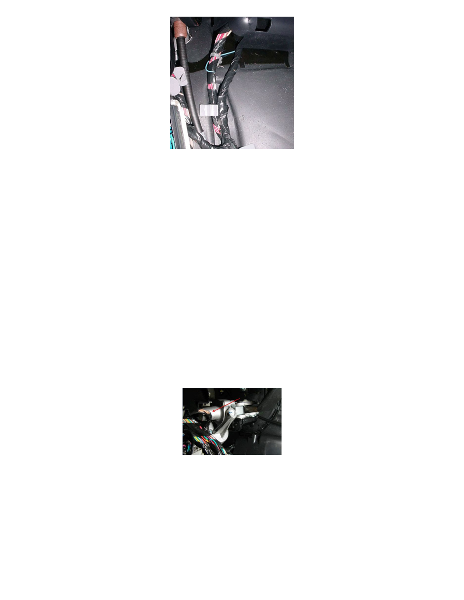
7. Inspect how the IP branch to C202 is routed. Reroute the harness as necessary to match the correct routing in the photo as shown. In order to route
the IP harness branch correctly (behind the junction block-left I/P), remove the cover from the junction block-left I/P, unseat the junction block
from the bracket.
8. Disconnect C202. Route the harness such that it lies between the "goalposts" of the junction block bracket. Seat the junction block to the bracket
(harness will now be under the junction block).
9. Secure the harness by seating the grey offset retaining clip to the dashmat (or brown "buddy clip" if present - usually on SUV's only). Reconnect
C202.
10. Connect the negative battery cable. Refer to Battery Negative Cable Disconnection and Connection in SI.
11. Clear any DTCs that may be present with a scan tool and verify the proper operation of the vehicle.
Chafed IP Wiring Harness at Left Side Junction Block Mounting Bracket
1. Turn OFF the ignition and all accessories.
2. Disconnect the negative battery cable. Refer to Battery Negative Cable Disconnection and Connection in SI.
3. Remove the left side junction block. Refer to Instrument Panel Electrical Center or Junction Block Replacement - Left Side in SI.
4. Inspect for chafed/shorted wiring at the mounting bracket.
If the wiring is damaged, repair as needed. Refer to Wiring Systems and Power Management > Diagnostic Information and Procedures in SI.
5. Protect the harness by covering the sharp edge with butyl tape or a suitable material. Secure the harness as needed.
6. Replace the left side junction block. Refer to Instrument Panel Electrical Center or Junction Block Replacement - Left Side in SI.
7. Connect the negative battery cable. Refer to Battery Negative Cable Disconnection and Connection in SI.
8. Clear any DTCs that may be present with a scan tool and verify the proper operation of the vehicle.
Chafed Wiring Harness at Adjustable Pedals Motor
1. Turn OFF the ignition and all accessories.
2. Disconnect the negative battery cable. Refer to Battery Negative Cable Disconnection and Connection in SI.
3. Inspect the wiring harness for chafed/shorted wiring at the adjustable pedals motor as shown.
4. If the wiring is damaged, repair as needed. Refer to Wiring Systems and Power Management > Diagnostic Information and Procedures in SI.
5. Protect the harness by covering the sharp edge with butyl tape or a suitable material. Secure the harness as needed.
6. Connect the negative battery cable. Refer to Battery Negative Cable Disconnection and Connection in SI.
7. Clear any DTCs that may be present with a scan tool and verify the proper operation of the vehicle.
Chafed Wiring Harness at Transmission
1. Turn OFF the ignition and all accessories.
2. Disconnect the negative battery cable. Refer to Battery Negative Cable Disconnection and Connection in SI.
3. Raise the vehicle. Refer to Lifting and Jacking the Vehicle in SI.
4. Support the transmission with a transmission jack.
5. Remove the transmission support crossmember. Refer to Transmission Support Crossmember Replacement in SI.