
Sierra 1500 2WD V8-5.3L (2008)
Heated Glass Element: Testing and Inspection
Rear Window Defogger Malfunction
Diagnostic Instructions
*
Perform the Diagnostic System Check - Vehicle prior to using this diagnostic procedure. See: Testing and Inspection/Initial Inspection and
Diagnostic Overview/Diagnostic System Check - Vehicle
*
Review Strategy Based Diagnosis for an overview of the diagnostic approach.
*
Diagnostic Procedure Instructions provides an overview of each diagnostic category.
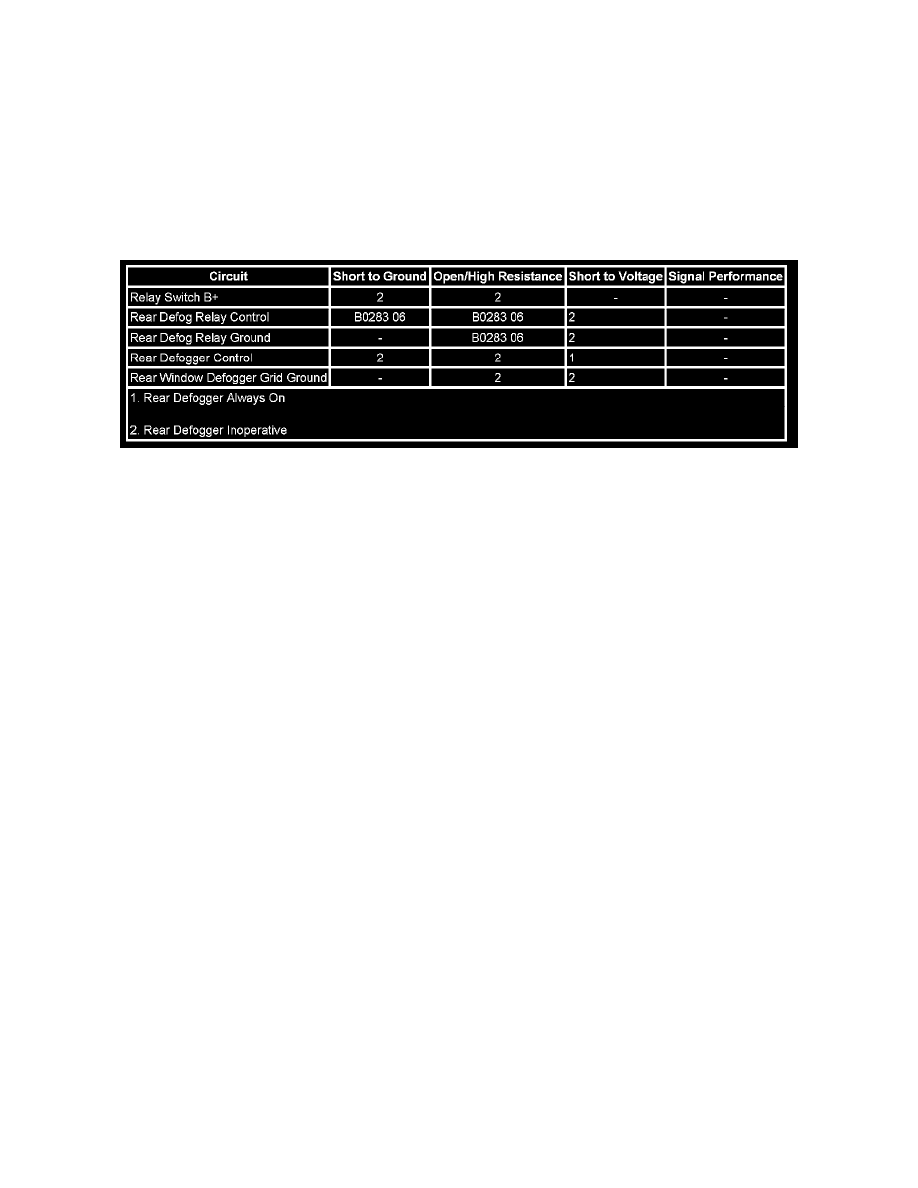
Diagnostic Fault Information
Circuit/System Description
When the rear defogger button is pressed, voltage is supplied to the relay coil by the HVAC control module which also illuminates the rear window
defogger indicator. B+ voltage is supplied at all times to the relay switched input and the relay coil is always grounded. This allows battery positive
voltage from the relay switched input through the switch contacts and out the relay switched output to the rear window defogger. Ground for the rear
defogger grid is provided by G304 or G307.
Circuit/System Verification
1. Ignition ON, observe the scan tool Rear Defrost State parameter while pressing the rear window defogger switch. The parameter should change
between On and Off.
^
If the parameter does not change between the commanded states, replace the HVAC module.
2. Observe the operation of the rear window defogger indicator while pressing the rear window defogger switch. The indicator should turn ON or
OFF each time the rear window defogger switch is pressed.
^
If the indicator does not turn ON or OFF with each switch press, replace the HVAC module.
3. Command the rear window defogger ON and OFF with a scan tool. The rear window defogger should turn ON and OFF when changing between
the commanded states.
Circuit/System Testing
1. Ignition OFF, disconnect the REAR DEFOG relay.
2. Test for less than 1.0 ohm between the ground circuit terminal 85 and ground.
^
If greater than the specified range, test the ground circuit for an open/high resistance.
3. Ignition ON, verify that a test lamp does not illuminate between the control circuit terminal 87 and ground.
^
If the test lamp illuminates, test the control circuit for a short to voltage.
4. Verify that a test lamp illuminates between the B+ circuit terminal 30 and ground.
^
If the test lamp does not illuminate, test the B+ circuit for a short to ground or an open/high resistance.
5. Ignition OFF, disconnect the X2 harness connector at the defogger grid.
6. Test for less than 5 ohms between the defogger grid ground circuit terminal A and ground.