
Sierra 1500 2WD V8-5.3L Hybrid (2004)
4. Insert the terminal into the crimp tool until the core wings are flush with the anvil on the crimp tool. Be sure that the wings are pointed toward the
crimp tool former and release the spring locator. The locator will hold the terminal in place. Inspect the alignment of the terminal wings with the
crimp tool former. If the terminal wings are wider than the crimp tool former, remove the terminal and bend the terminal wings in slightly.
5. Place stripped wire into terminal.
6. Crimp the new terminal to the wire. If a jam occurs, press the emergency release to open applicator.
REPLACEMENT PROCEDURE
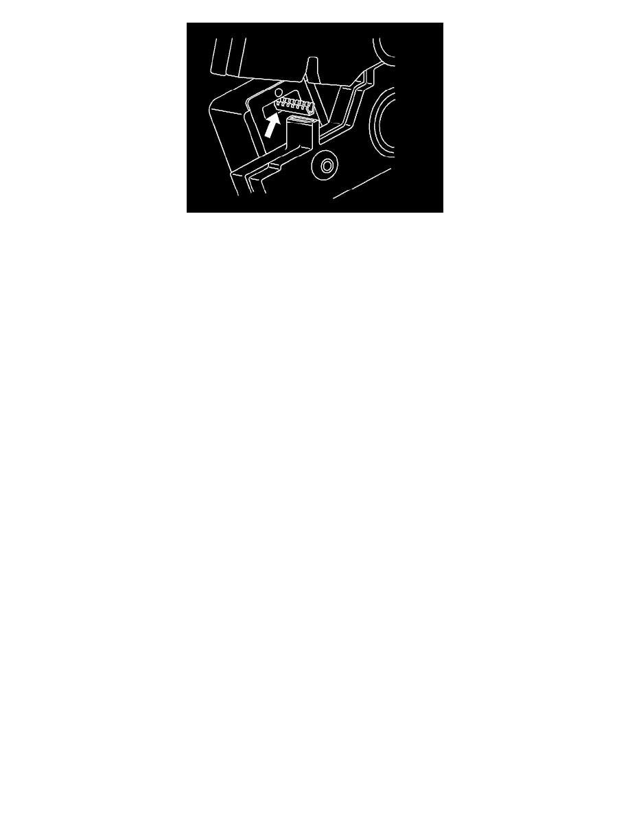
After the terminal is crimped to the wire perform the following procedure in order to replace Micro-Pack 100 terminals.
1. Slide the new terminal into the correct cavity at the back of the connector.
2. Push the terminal into the connector until it locks into place. The new terminal should be even with the other terminals. Insure that the terminal is
locked in place by gently pulling on the wire.
3. To assemble the connector, reverse the Terminal Removal Procedure.
Repairing Connector Terminals
REPAIRING CONNECTOR TERMINALS
TOOLS REQUIRED
J 38125-D Terminal Repair Kit
Use the following repair procedures in order to repair the following:
-
Push to Seat terminals
-
Pull to Seat terminals
-
Weather Pack(R) terminals
Some terminals do not require all of the steps shown. Skip the steps that do not apply for your immediate terminal repair. The J 38125-D contains further
information.
1. Cut off the terminal between the core and the insulation crimp. Minimize any wire loss.
For Weather Pack(R) terminals, remove the seal.
2. Apply the correct seal per gage size of the wire.
For Weather Pack(R) terminals, slide the seal back along the wire in order to enable insulation removal.
3. Remove the insulation.
4. For Weather Pack(R) terminals only, align the seal with the end of the cable insulation.
5. Position the strip in the terminal.
For Weather Pack(R) terminals, position the strip and seal in the terminal.
6. Hand crimp the core wings.
7. Hand crimp the insulation wings.
For Weather Pack(R) terminals, hand crimp the insulation wings around the seal and the cable.
8. Solder all of the hand crimp terminals excepting Micro-Pack 100 World terminals. Soldering Micro-Pack 100 World terminals may damage the
terminal.
Circuit Protection - Circuit Breakers
CIRCUIT PROTECTION - CIRCUIT BREAKERS
A circuit breaker is a protective device that is designed to open the circuit when a current load is in excess of the rated breaker capacity. If there is a short
or other type of overload condition in the circuit, the excessive current will open the circuit between the circuit breaker terminals. Two types of circuit
breakers are used.