
Sierra 1500 2WD V8-5.3L VIN Z Flex Fuel (2006)
3. Push the wire side of the terminal that is being removed toward the connector and hold it in position.
4. Insert the J 38125-561 tool into the 2 cavities on each side of the terminal at the front of the connector and push until you feel the tool disengage
the terminal retainers. See the release tool cross reference in the Reference Guide of the J-38125 to ensure that the correct release tool is used.
5. Carefully pull the terminal out of the connector. Always remember never use force when pulling a terminal out of a connector. If the terminal is
difficult to remove, repeat the entire procedure.
TERMINAL REPAIR PROCEDURE
Use the appropriate terminal and follow the instructions in the J-38125.
Bosch Connectors (0.64)
BOSCH CONNECTORS (0.64)
TOOLS REQUIRED
J-38125 Terminal Repair Kit
TERMINAL REMOVAL PROCEDURE
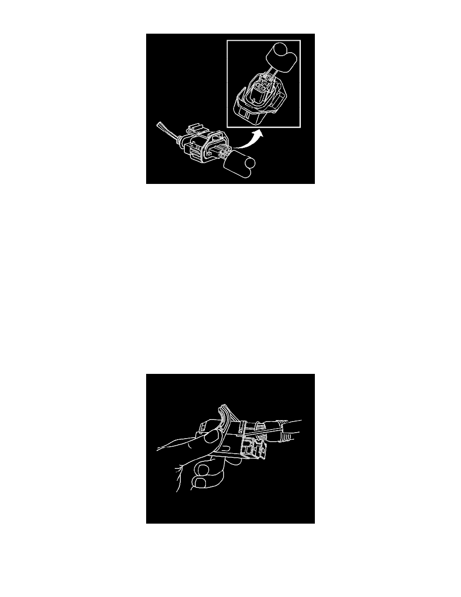
1. Locate the lever lock on the wire dress cover. While pressing the lock, pull the lever over and past the lock until the lever is at the end of its travel.
2. Disconnect the connector from the component.
3. Pull the rubber boot that covers the wires back to expose the end of the connector dress cover.
4. Place the connector locking lever in the center of the connector.
5. Locate the 2 dress cover locking tabs that are on the wire end of the connector. Insert a small flat-bladed tool between the cover and connector
body and pry up.