
Sierra 1500 4WD V6-4.3L (2008)
8. Remove the crossmember (2) from the crossmember mount (3).
9. Remove the torsion bar from the crossmember.
Important: The left and right torsion bars are different and are not interchangeable.
10. Remove the torsion bars from the vehicle.
Installation Procedure
1. Position the torsion bar in the lower control arm.
2. Install the torsion bar in the crossmember (2) on the crossmember mount (3).
Notice: Refer to Fastener Notice .
3. Install the torsion bar crossmember bolt (4) in the weld nut (1).
Tighten the crossmember bolt to 95 N.m (70 lb ft).
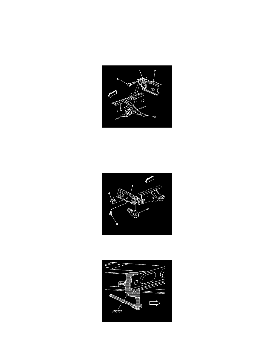
4. Install the adjustment arm (2) in the crossmember (1).
5. Install the adjuster bolt (3) and the adjuster nut (4).
6. Install the torsion bar into the adjustment arm until the torsion bar is fully seated.
7. Install the J 36202 to the adjustment arm and the crossmember.
8. Using the J 36202 , increase the tension on the adjustment arm to load the torsion bar.
9. Turn the adjuster bolt the same amount of turns as it took to remove it.