
Sierra 1500 4WD V8-5.3L VIN B (2005)
ASSEMBLING AND CODING IGNITION LOCK CYLINDER
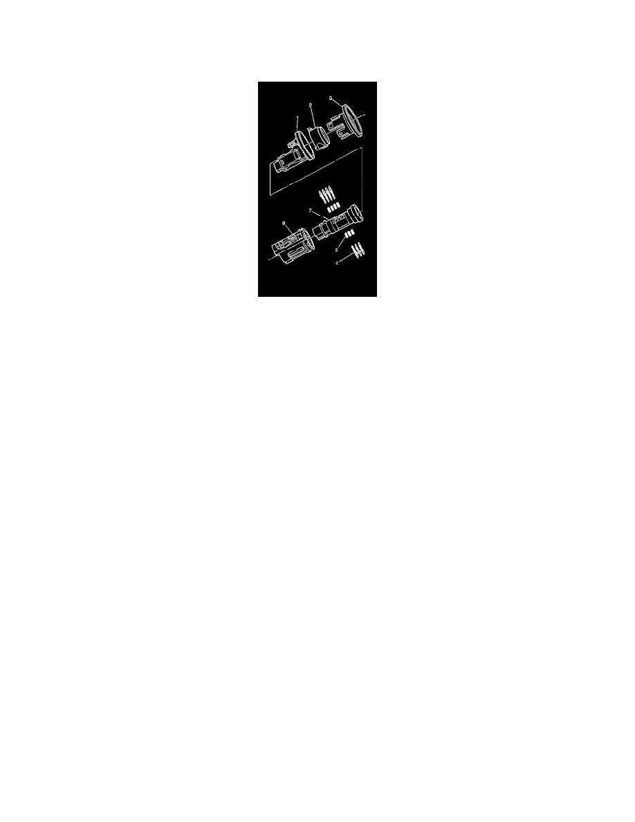
The ignition lock cylinder only uses seven of the ten cut positions, 3 through 9. The tumbler positions are staggered from side to side, four on one side
and three on the other.
1. Hold the cylinder (7) so that the side with four tumbler spring wells is facing up.
2. Insert tumbler springs (5) into the four spring wells.
3. The first tumbler to be loaded will be the 3rd key cut position (the 3rd number in the key code). Install the first tumbler (4) in the slot nearest the
front of the lock cylinder, this is the side the key would be inserted from.
4. Install the three remaining tumblers on this side of the lock cylinder, key cut positions 5, 7 and 9.
5. Snap the tumblers into place with light hand pressure.
6. Check for correct loading of the tumblers (4) by inserting the key into the cylinder (7). All of the tumblers should be flush with the lock cylinder.
7. Turn the cylinder (7) so that the side with the 3 tumbler spring wells is facing up.
8. Insert the tumbler springs (5) into the three spring wells.
9. Install the tumbler (4) for the key cut position 4 into the slot nearest to the front of the lock cylinder.
10. Install the 2 remaining tumblers, key cut positions 6 and 8, on this side of the lock cylinder.
11. Snap the tumblers into place with light hand pressure.
12. Inspect for correct loading of the tumblers (4) by inserting the key into cylinder (7). All of the tumblers should be flush with the lock cylinder.
13. Lightly lubricate the tumblers (4) surfaces using the provided lubricant.
14. With the key inserted into the housing, align the retaining bar with the groove on the inside diameter of the cylinder housing. This groove extends
through to the back of the lock housing (6).
15. Lifting the flat spring and button, install the cylinder (7) into the cylinder housing (6). The retainer bar snaps into place when the cylinder (7) is
fully seated.
ASSEMBLING AND CODING DOOR LOCK CYLINDER
The door lock cylinder only uses seven of the ten cut positions, 3 through 9. The tumbler positions are staggered from side to side, 4 on one side and 3
on the other. The left and right door lock cylinders are identical. The lock pawl determines the side of the vehicle the lock cylinder is on.