
Sierra 1500 4WD V8-5.3L VIN T (2004)
11. If only the left side seal was removed, perform the following step. Install the inner axle shaft into the differential case side gear using a soft-faced
mallet until the retaining ring on the inner axle shaft is fully seated within the groove in the differential case side gear.
-
Pull back on the inner axle shaft to ensure that the inner axle shaft is properly retained in the differential case side gear.
12. If only the left side seal was removed, perform the following step. Install the wheel drive shaft to the inner axle shaft.
Notice: Use the correct fastener in the correct location. Replacement fasteners must be the correct part number for that application. Fasteners requiring
replacement or fasteners requiring the use of thread locking compound or sealant are identified in the service procedure. Do not use paints, lubricants,
or corrosion inhibitors on fasteners or fastener joint surfaces unless specified. These coatings affect fastener torque and joint clamping force and may
damage the fastener. Use the correct tightening sequence and specifications when installing fasteners in order to avoid damage to parts and systems.
13. If only the left side seal was removed, perform the following step. Install the wheel drive shaft to the inner axle shaft bolts.
-
Tighten the wheel drive shaft to inner axle shaft bolts to 79 Nm (58 lb ft).
14. Fill the differential carrier assembly. Use the correct fluid.
15. Lower the vehicle.
Differential Drive Pinion Flange/Yoke, Seal, and Dust Deflector Replacement
Differential Drive Pinion Flange/Yoke, Seal, and Dust Deflector Replacement - Front
^
Tools Required
-
J 8614-01 Flange and Pulley Holding Tool
-
J 36366 Pinion Oil Seal Installer
Removal Procedure
1. Raise the vehicle. Refer to Vehicle Lifting.
2. Remove the tire and wheel assemblies.
3. Remove the brake calipers.
4. Remove the differential carrier assembly shield, if equipped.
5. Reference mark the relationship of the propeller shaft to the front axle pinion yoke.
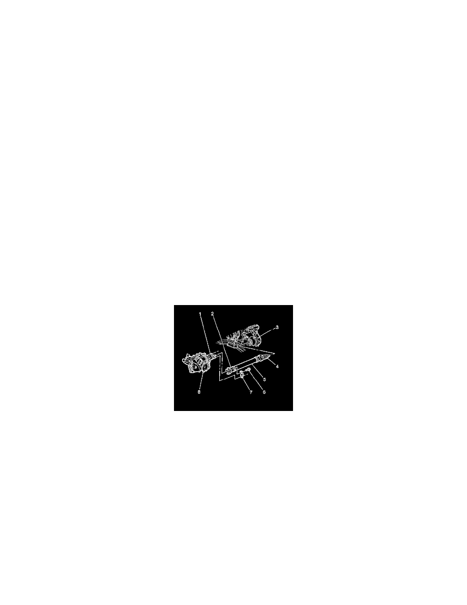
6. Remove the yoke retainer bolts (6) and the yoke retainers (7) from the front axle pinion yoke (1).
7. Disconnect the propeller shaft universal joint (2) from the front axle pinion yoke (1). Wrap the bearing caps with tape in order to prevent the loss
of bearing rollers.
Notice:
When removing the propeller shaft, do not attempt to remove the shaft by pounding on the yoke ears or using a tool between the yoke and the
universal joint. If the propeller shaft is removed by using such means, the injection joints may fracture and lead to premature failure of the joint.
8. Support the propeller shaft and move out of the way as necessary.