
Sierra 1500 4WD V8-5.3L VIN Z Flex Fuel (2005)
13. If the brake rotor cannot be removed, perform the following:
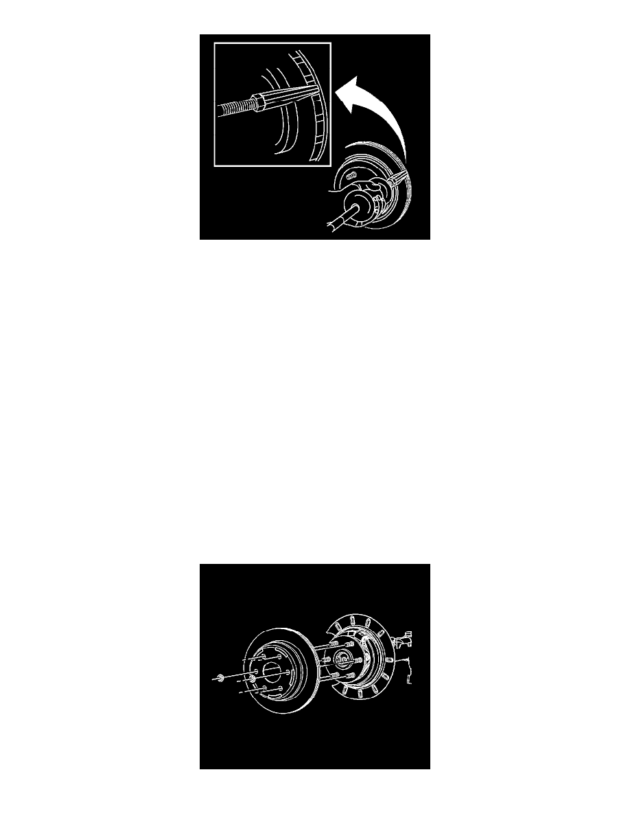
1. Assemble J-46277 to J2619-01.
2. Insert J-46277 between the rotor friction surfaces in the vent section of the rotor. DO NOT place the J-46277 on the rotor friction surface.
3. Using J-46277 and J2619-01 remove the rotor from the hub.
4. Inspect the park brake components for the following conditions:
^
Bent or broken hold down spring
^
Broken, cracked or worn brake shoe lining
^
Bent or damaged brake shoe
^
Worn, bent or damaged back plate
5. If any of these conditions are found replace the affected parts.
Installation Procedure
1. Important: Whenever the brake rotor has been separated from the hub/axle flange, any rust or contaminants should be cleaned from the hub/axle
flange and the brake rotor mating surfaces. Failure to do this may result in excessive assembled lateral runout (LRO) of the brake rotor, which
could lead to brake pulsation.
Use the J42450-A to clean all rust and contaminants from the mating surface of the hub flange.
2. Use the J41013 to clean all rust and contaminants from the inside diameter of the hat section of the brake rotor to prevent any foreign material
from getting between the brake rotor and the hub flange.
3. Inspect the mating surfaces of the hub/axle flange and the rotor to ensure that there are no foreign particles or debris remaining.
4. Align the rotor to its original position on the hub, if applicable, and install the rotor.
5. If the rotor was removed and installed as part of a brake system repair, measure the assembled Lateral Runout (LRO) of the rotor to ensure
optimum performance of the disc brakes.
6. If the rotor assembled LRO measurement exceeds the specification, bring the LRO to within specifications.