
Sierra 1500 4WD V8-6.0L (2007)
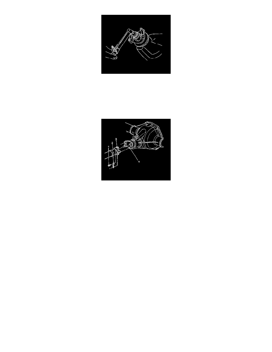
8. Measure the rotating torque of the pinion. Compare this measurement with the rotating torque recorded during removal.
Tighten the nut in small increments, as needed, until the rotating torque is 0.40-0.57 N.m (3- 5 lb in) greater than the rotating torque
recorded during removal.
9. Once the specified torque is obtained, rotate the pinion several times to ensure the bearings have seated. Recheck the rotating torque and adjust if
necessary.
10. Install the propeller shaft (3) to the pinion yoke (4).
Align the reference marks made during removal.
11. Install the propeller shaft yoke retaining clamps and the bolts.
Tighten the propeller shaft yoke retaining clamp bolts to 25 N.m (18 lb ft).
12. Install the axle shafts (10.5 inch, 11.5 inch axle).
13. Install the brake rotors (8.6 inch, 9.5 inch axles).
14. Install the brake calipers (8.6 inch, 9.5 inch axles).
15. Install the tire and wheel assemblies.
16. Inspect and add axle lubricant to the axle housing, if necessary.
17. Lower the vehicle.
Drive Pinion Flange/Yoke and/or Oil Seal Replacement (8.6 Inch Axle w/Drum Brakes)
Drive Pinion Flange/Yoke and/or Oil Seal Replacement (8.6 Inch Axle w/Drum Brakes)
Tools Required
*
J 8614-01 Flange/Pulley Holding Tool
*
J 22388 Rear Axle Pinion Oil Seal Installer - Rear
Removal Procedure
Important: Observe and mark the positions of all the driveline components, relative to the propeller shaft and the axles, prior to disassembly.
These components include the propeller shafts, drive axles, pinion flanges, output shafts, etc. Reassemble all the components in the exact places
in which you removed the parts. Follow any specifications, torque values, and any measurements made prior to disassembly.