
Sierra 2500 2WD V8-6.6L DSL Turbo (2007)
Installation Procedure
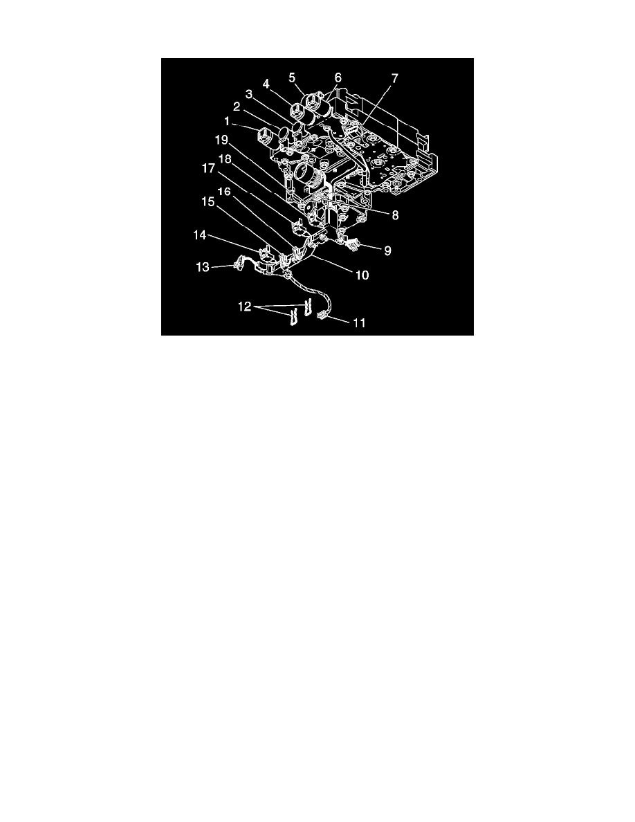
1. Align the tabs on the new wiring harness (10) U-channel with the solenoid retainer slots for SS3 (3) and SS2 (2) on the control valve assembly.
Install the solenoid retainers (12) for the SS3 (3) and SS2 (2) solenoids.
Important: The internal wiring harness connectors should be in the correct position for installation because of their pre-assembled
position in the U-channel.
2. Attach the internal wiring harness (10) connectors to the solenoids, the IMS, and the TFP switch.
*
Connector (8) goes to SS1 (5)
*
Connector (9) goes to the TFP switch (7)
*
Connector (11) goes to the MAIN MOD solenoid (19)
*
Connector (13) goes to the IMS
*
Connector (14) goes to the TCC PCS (1)
*
Connector (15) goes to SS2 (2)
*
Connector (16) goes to SS3 (3)
*
Connector (17) goes to PCS1 (4)
*
Connector (18) goes to PCS2 (6)