
Sierra 2500 Denali 2WD V8-6.0L (2011)
8. Continue to apply pressure and rock the cover until the second locking leg is unseated. Repeat procedure for the other side of the dress cover and
remove the cover.
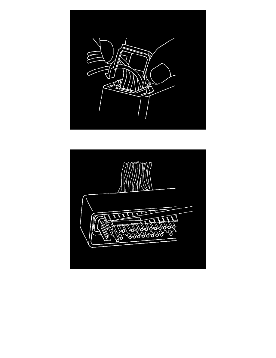
9. Use J-38125-12A to gently lift the terminal retaining tab while gently pulling the wire out of the back of the connector. Always remember never
use force when pulling a terminal out of a connector.
10. If the terminal is severely bent or damaged, it may be possible on some connectors to push the wire out of the front of the connector instead of
pulling it through. This will prevent damage to the internal seals of the connector. Once the terminal is pushed out of the connector, cut the wire as
close to the terminal as possible and pull the wire through the connector.
11. Repair the terminal by following the Repairing Connector Terminals (Terminated Lead Repair) (See: General Electrical Diagnostic
Procedures/Connector Repairs/Repairing Connector Terminals (Terminated Lead Repair))Repairing Connector Terminals (Terminal Repair) (
See: General Electrical Diagnostic Procedures/Connector Repairs/Repairing Connector Terminals (Terminal Repair)) procedure.
12. Insert the repaired terminal back into the cavity. Repeat the diagnostic procedure to verify the repair and reconnect the connector bodies.
Terminal Insertion Procedure
After the terminal is crimped to the wire perform the following procedure in order to replace Micro-Pack 100 terminals.