
Sierra 2500 Denali 2WD V8-6.0L (2011)
-
Wear the Insulation gloves at all times when working with the high voltage battery assembly, whether the system is energized or not.
Failure to follow the procedure exactly as written may result in serious injury or death.
Caution: Refer to Test Probe Caution (See: Service Precautions/Vehicle Damage Warnings/Test Probe Caution).
The following procedure measures the voltage at a selected point in a circuit.
1. Disconnect the electrical harness connector for the circuit being tested, if necessary.
2. Enable the circuit and/or system being tested. Use the following methods:
*
Turn ON the ignition, with the engine OFF.
*
Turn ON the engine.
*
Turn ON the circuit and/or system with a scan tool in Output Controls.
*
Turn ON the switch for the circuit and/or system being tested.
3. Select the V (AC) or V (DC) position on the DMM.
4. Connect the negative lead of the DMM to a good ground.
5. Connect the positive lead of the DMM to the point of the circuit to be tested.
6. The DMM displays the voltage measured at that point.
Measuring Voltage Drop
Measuring Voltage Drop
Special Tools
EL 39200 - Digital Multimeter (DMM)
For equivalent regional tools, refer to Special Tools (See: Power and Ground Distribution/Tools and Equipment).
Caution: Refer to Test Probe Caution (See: Service Precautions/Vehicle Damage Warnings/Test Probe Caution).
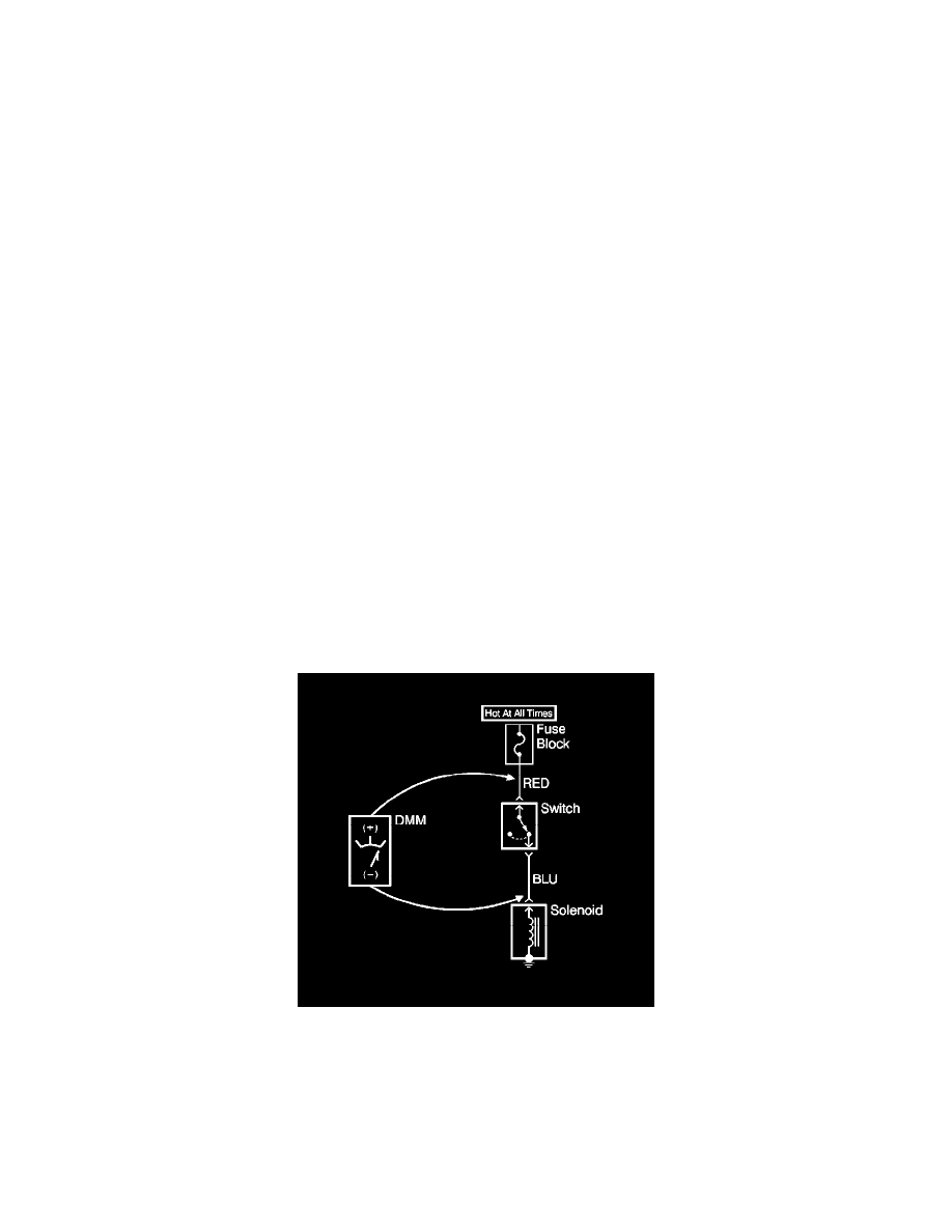
The following procedure determines the difference in voltage potential between 2 points.
1. Set the Digital Multimeter (DMM) to the V (DC) position.
2. Connect the positive lead of the DMM to one point of the circuit to be tested.
3. Connect the negative lead of the DMM to the other point of the circuit.
4. Operate the circuit.
5. The DMM displays the difference in voltage between the 2 points.
Probing Electrical Connectors
Probing Electrical Connectors