
Sierra 2500 Denali 2WD V8-6.0L (2011)
*
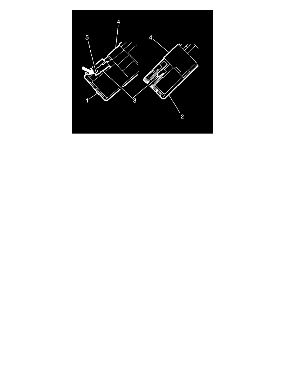
The cavity on the left (1) is a 2.8 mm cavity and the cavity on the right (2) is a 0.64 mm cavity.
*
Place the tip of the connector terminal release tool onto the connector lance (3) and deflect the lance to the right (5) to release the lock. Hold
this released position.
*
Holding the lance in the released position, slightly pull on the suspect terminal to remove it from the connector housing. The side TPA (4) is a
secondary lock.
4. Repair the terminal by following the Repairing Connector Terminals (Terminated Lead Repair) (See: General Electrical Diagnostic
Procedures/Connector Repairs/Repairing Connector Terminals (Terminated Lead Repair))Repairing Connector Terminals (Terminal Repair) (
See: General Electrical Diagnostic Procedures/Connector Repairs/Repairing Connector Terminals (Terminal Repair)) procedure.
5. Insert the repaired terminal back into the cavity. Repeat the diagnostic procedure to verify the repair and reconnect the connector bodies.
Kostal Connectors (Glow Plug Control Module)
Kostal Connectors (Glow Plug Control Module)
Special Tools
*
EL-38125-580 - Terminal Release Tool Kit
*
J-38125-24 - Terminal Release Tool
*
J-38125-560 - Terminal Release Tool
For equivalent regional tools, refer to Special Tools (See: Tools and Equipment).
Terminal Removal Procedure