
Sierra 2500 Denali 2WD V8-6.0L (2011)
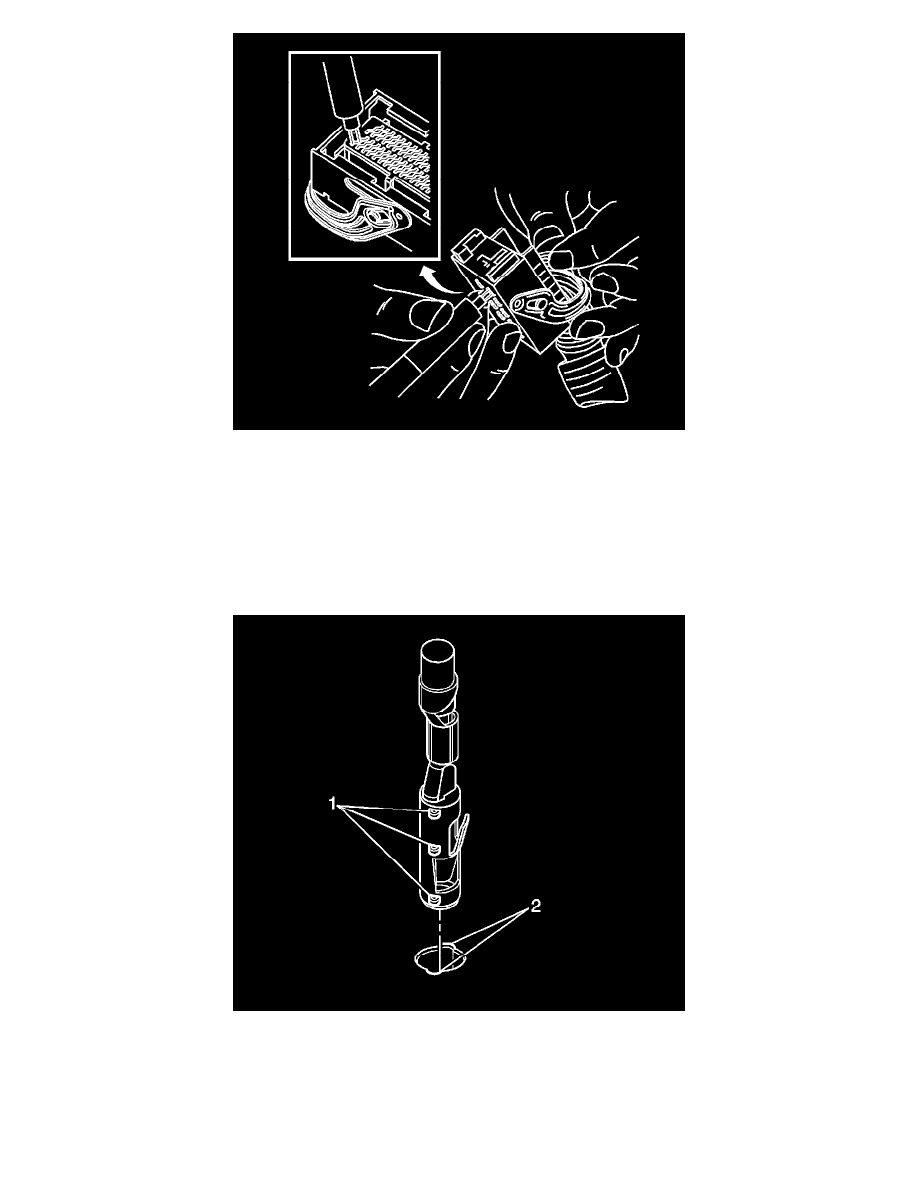
11. Insert the J-38125-560 into the 2 triangular cavities on each side of the terminal at the front of the connector.
12. Carefully pull the terminal out of the connector. Always remember never use force when pulling a terminal out of a connector. If the terminal is
difficult to remove, repeat the entire procedure.
13. Repair the terminal by following the Repairing Connector Terminals (Terminated Lead Repair) (See: General Electrical Diagnostic
Procedures/Connector Repairs/Repairing Connector Terminals (Terminated Lead Repair))Repairing Connector Terminals (Terminal Repair) (
See: General Electrical Diagnostic Procedures/Connector Repairs/Repairing Connector Terminals (Terminal Repair)) procedure.
14. Insert the repaired terminal back into the cavity. Repeat the diagnostic procedure to verify the repair and reconnect the connector bodies.
Terminal Insertion Procedure
1. Prior to installation the terminal must be aligned so the (1) coding lugs align with the (2) coding grooves on the connector.
2. Once the terminal is aligned, slide the terminal into the cavity until the retainer has engaged in the cavity of the connector.
3. Slide the TPA in the connector body and seat it using a small flat bladed tool. The TPA is seated when it is flush with the contact housing.
4. Secure the wires to the connector body using a tie wrap and replace the dress cover and grommet.
Bosch Connectors (2.8 JPT)