
Sierra 2500 Denali 2WD V8-6.0L (2011)
Wheel Bearing: Service and Repair
Front Wheel Hub, Bearing, and Seal Replacement (2500, 3500)
Front Wheel Hub, Bearing, and Seal Replacement (2500, 3500)
Removal Procedure
Caution: Never place vehicle on the ground with the halfshaft removed or the halfshaft nut torqued improperly. Otherwise, bearing seals may
become dislodged causing premature wear and/or damage to the hub and bearing assembly.
1. Raise and support the vehicle. Refer to Lifting and Jacking the Vehicle (See: Wheels and Tires/Vehicle Lifting/Service and Repair).
2. Remove the tire and wheel. Refer to Tire and Wheel Removal and Installation (See: Wheels and Tires/Service and Repair).
3. Remove the brake rotor. Refer to Front Brake Rotor Replacement (JD9, JF3, JF7, JG4) (See: Brakes and Traction Control/Disc Brake
System/Brake Rotor/Disc/Service and Repair/Removal and Replacement/Front Brake Rotor Replacement (JD9, JF3, JF7, JG4))Front Brake Rotor
Replacement (J90, J96) (See: Brakes and Traction Control/Disc Brake System/Brake Rotor/Disc/Service and Repair/Removal and
Replacement/Front Brake Rotor Replacement (J90, J96))Front Brake Rotor Replacement (J95) (See: Brakes and Traction Control/Disc Brake
System/Brake Rotor/Disc/Service and Repair/Removal and Replacement/Front Brake Rotor Replacement (J95)).
4. Remove the wheel speed sensor from the wheel hub and bearing. Refer to Front Wheel Speed Sensor Replacement (See: Brakes and Traction
Control/Antilock Brakes / Traction Control Systems/Wheel Speed Sensor/Service and Repair/Front Wheel Speed Sensor Replacement/Less than
3900 kg (8600 lb) GVW)
Note: Steps 6 thru 8 applies to those vehicles equipped with 4WD
5. Remove the wheel driveshaft nut retaining cover.
Caution: Wheel drive shaft boots, seals and clamps should be protected from sharp objects any time service is performed on or near the wheel
drive shaft(s). Damage to the boot(s), the seal(s) or the clamp(s) may cause lubricant to leak from the joint and lead to increased noise and possible
failure of the wheel drive shaft.
6. Wrap shop towel around the inner and outer wheel drive shaft boot.
7. Separate the wheel driveshaft assembly from the wheel hub and bearing. Refer to Wheel Drive Shaft Replacement (1500) (See: Transmission and
Drivetrain/Drive Axles, Bearings and Joints/Axle Shaft Assembly/Service and Repair/Wheel Drive Shaft Replacement (1500))Wheel Drive Shaft
Replacement (2500/3500) (See: Transmission and Drivetrain/Drive Axles, Bearings and Joints/Axle Shaft Assembly/Service and Repair/Wheel
Drive Shaft Replacement (2500/3500)).
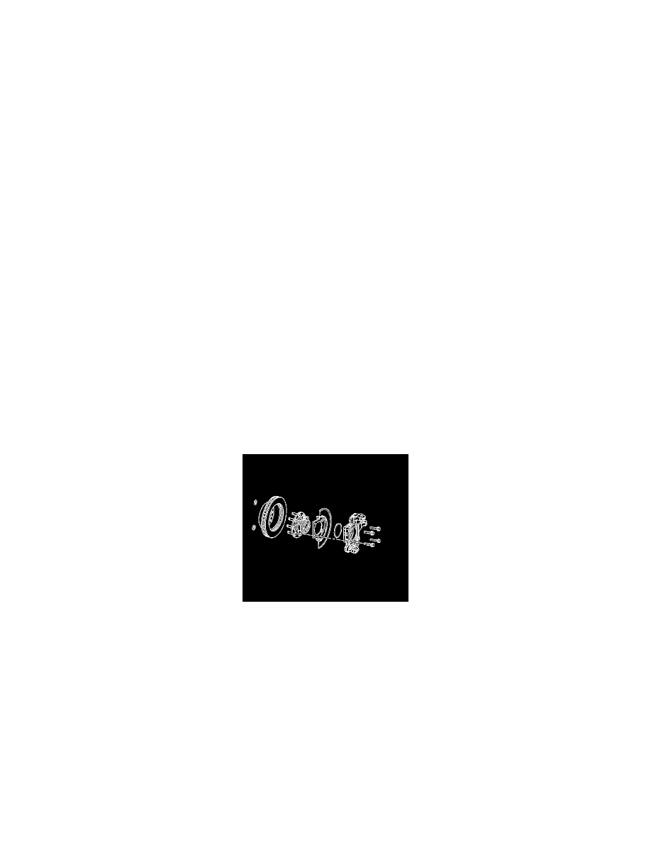
8. Remove the wheel hub and bearing mounting bolts.
9. Remove the wheel hub and bearing and splash shield from the vehicle.
10. Remove the O-ring seal from the steering knuckle bore.
11. Clean and inspect the O-ring seal.
12. Replace the seal if the following conditions exist:
*
Nicks
*
Cuts
*
Dry or brittle
*
Compression set
Installation Procedure
1. Clean all corrosion or contaminates from the steering knuckle bore and the hub and bearing assembly.
2. Lubricate the steering knuckle bore with wheel bearing grease or the equivalent.