
Sierra 2500 Denali 2WD V8-6.0L (2011)
Note: Be careful not to angle or rock the J-38125-21 tool when inserting it into the connector or the tool may break.
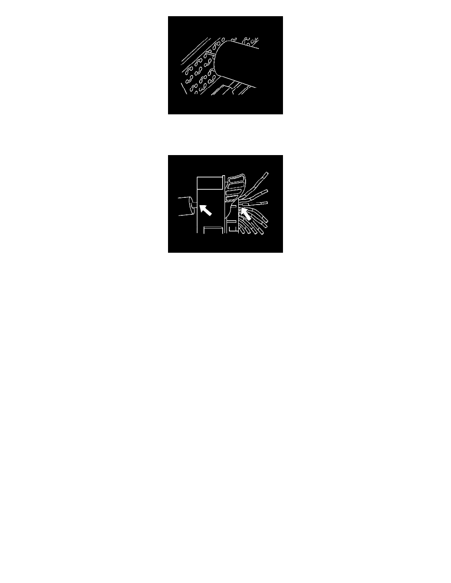
6. Insert the J-38125-21 tool into the round canal between the terminals cavities at the front of the connector.
7. While holding the removal tool in place, gently pull the wire out of the back of the connector. Always remember never use force when pulling a
terminal out of a connector.
8. Repair the terminal by following the Repairing Connector Terminals (Terminated Lead Repair) (See: General Electrical Diagnostic
Procedures/Connector Repairs/Repairing Connector Terminals (Terminated Lead Repair))Repairing Connector Terminals (Terminal Repair) (
See: General Electrical Diagnostic Procedures/Connector Repairs/Repairing Connector Terminals (Terminal Repair)) procedure.
9. Insert the repaired terminal back into the cavity. Repeat the diagnostic procedure to verify the repair and reconnect the connector bodies.
Delphi Connectors (Micro-Pack 100W)
Delphi Connectors (Micro-Pack 100W)
Special Tools
*
EL-38125-580 - Terminal Release Tool Kit
*
J-38125-12A - Terminal Release Tool
For equivalent regional tools, refer to Special Tools (See: Power and Ground Distribution/Tools and Equipment).
Terminal Removal Procedure
There are 2 styles of Micro-Pack 100W connectors. These connectors are very similar but use different terminals and have some minor physical
differences also.