
Sierra 3500 4WD V8-6.0L (2008)
16. Ignition OFF, disconnect the harness connector of the transmission control module (TCM).
17. Attempt to communicate with the EBCM. Communication should not be available.
^
If communication is established, test the serial data circuits for a short between them, short to ground or a short to voltage between the TCM
and the ECM. If the circuits test normal, replace the TCM.
18. Ignition OFF, connect the harness connector of the suspension control module. Disconnect the harness connector of the EBCM.
19. Attempt to communicate with the suspension control module. Communication should not be available.
^
If communication is established, test the serial data circuits for a short between them, short to ground or a short to voltage between the EBCM
and the TCM. If the circuits test normal, replace the EBCM.
20. Ignition OFF, disconnect harness connector C3 of the BCM.
21. Test for less than 1 volt between the high speed GMLAN serial data circuits of the DLC and ground.
^
If greater than the specified range, test the serial data circuit for a short to voltage.
22. Test for infinite resistance between the high speed GMLAN serial data circuit of the DLC and ground.
^
If less than the specified range, test the serial data circuit for a short to ground.
23. Test for infinite resistance between the high speed GMLAN serial data (+) and (-) circuits of the DLC.
^
If less than the specified range, test the serial data circuits for a short between them.
24. If the circuits test normal, replace the BCM.
Repair Instructions
Perform the Diagnostic Repair Verification after completing the repair. See: Testing and Inspection/Diagnostic Trouble Code Tests and Associated
Procedures/Verification Tests and Procedures
*
GMLAN Wiring Repairs
Scan Tool Does Not Communicate with Low Speed GMLAN Device
Scan Tool Does Not Communicate with Low Speed GMLAN Device
Diagnostic Instructions
*
Perform the Diagnostic System Check - Vehicle prior to using this diagnostic procedure. See: Testing and Inspection/Initial Inspection and
Diagnostic Overview/Diagnostic System Check - Vehicle
*
Review Strategy Based Diagnosis for an overview of the diagnostic approach.
*
Diagnostic Procedure Instructions provides an overview of each diagnostic category.
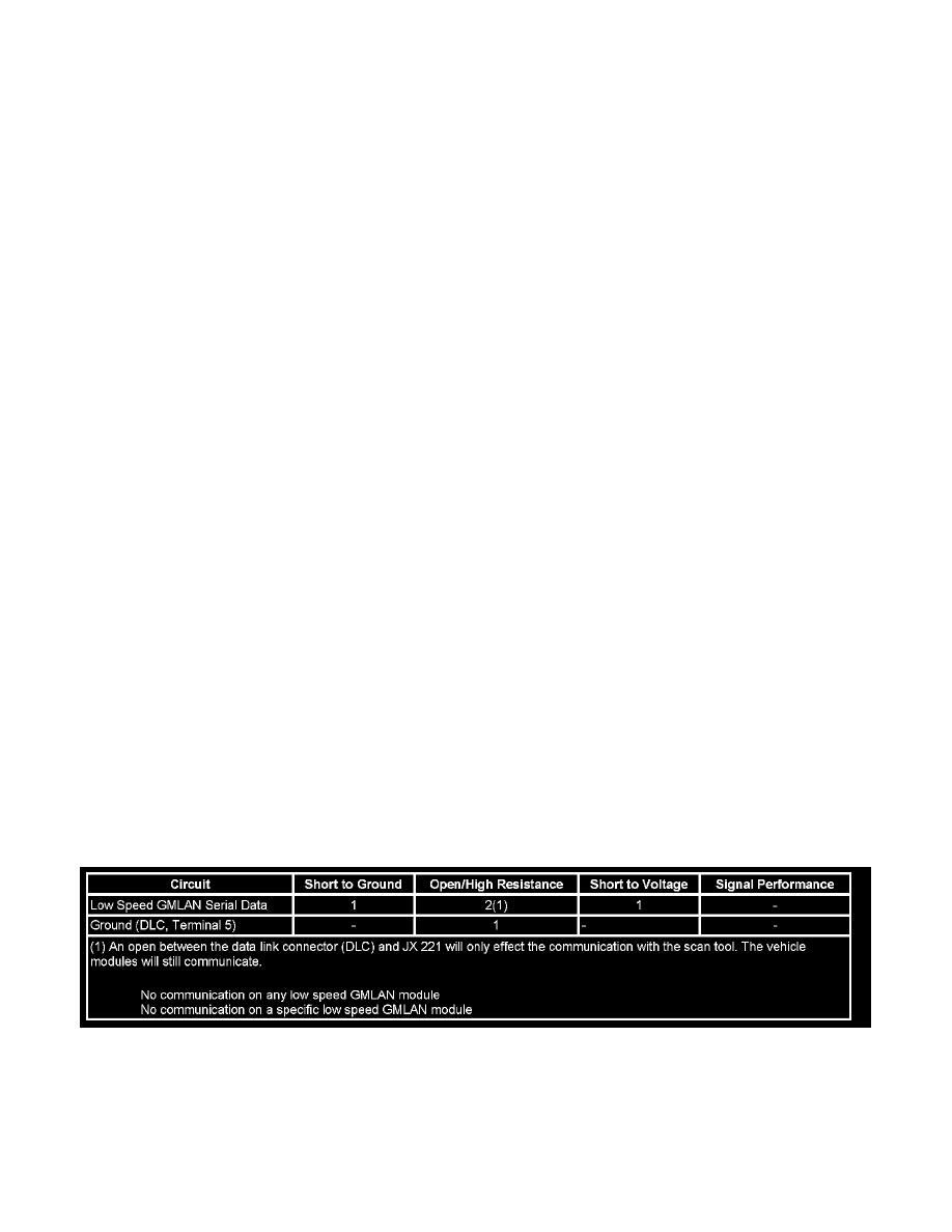
Diagnostic Fault Information
Circuit/System Description
Modules connected to the low speed GMLAN serial data circuit monitor for serial data communications during normal vehicle operation. Operating
information and commands are exchanged among the modules when the ignition switch is in any position other than OFF. The low speed GMLAN serial
data circuit must be operational for the vehicle to start so the vehicle theft deterrent (VTD) module and body control module (BCM) can communicate.
The low speed GMLAN serial data circuit uses JX 221 as the common connection between the modules and the data link connector (DLC).
Diagnostic Aids