
Sierra 3500 4WD V8-6.6L DSL Turbo (2007)
Fuel Pressure: Testing and Inspection
Fuel System Diagnosis
Fuel System Diagnosis
Diagnostic Instructions
*
Perform the Diagnostic System Check - Vehicle prior to using this diagnostic procedure. See: Testing and Inspection/Initial Inspection and
Diagnostic Overview/Diagnostic System Check - Vehicle
*
Review Strategy Based Diagnosis for an overview of the diagnostic approach.
*
Diagnostic Procedure Instructions provides an overview of each diagnostic category.
Circuit/System Description
Fuel is drawn by the fuel injection pump from the tank to the engine through the fuel supply lines. Fuel flows to the fuel filter/heater element housing,
which combines a water separator, a prime pump, fuel heater element and a filter element. A mechanical fuel injection pump at the front of the engine
valley includes the fuel supply pump and the high-pressure pump. The small section of the fuel pump assembly is the supply pump, which creates a
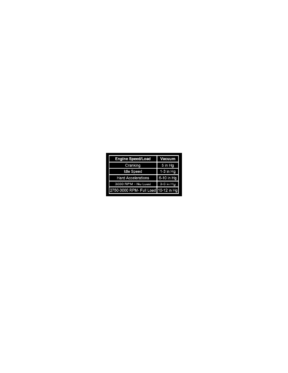
vacuum to pull fuel from the fuel tank to the high-pressure pump. The vacuum varies with engine load and speed as indicated by the table below. The
pump is engine-driven by the camshaft gear. From the high-pressure pump, the pressurized fuel flows to the left fuel rail. A balance pipe from the center
of the left rail then feeds the right fuel rail. Each fuel rail supplies one bank of 4 fuel injectors. The fuel rail pressure sensor is mounted in the end of the
right fuel rail. Fuel is used to cool and lubricate the fuel injectors and fuel injection pump. The fuel return system is designed to return this fuel to the fuel
tank. If the high side fuel pressure becomes excessive, the fuel rail pressure relief valve releases the fuel into the fuel return system. The return fuel
travels through the fuel cooler and then to the fuel tank.
Typical Supply Side Vacuum
Diagnostic Aids
An Engine Cranks but Will Not Run or Hard Start symptom may exist if air is being drawn into the fuel injection system due to the following conditions:
*
Deformed or cut O-rings at the fuel supply line connections
*
Improperly seated fuel supply line fittings
*
Porous or weathered rubber fuel supply lines
*
Fuel filter vent screw not tighten or cross threaded
*
Fuel filter not tighten properly
Circuit/System Verification
Observe the Actual Fuel Rail Pressure parameter with a scan tool. During engine cranking, the pressure should be at least 10 MPa. With the engine
running at idle the pressure should be close to the Desired Fuel Rail Pressure. As the engine speed increase, the Desired Fuel Rail Pressure and the
Actual Fuel Rail Pressure should be within 2 MPa of each other.
Circuit/System Testing
Important: Ensure that a sufficient amount of fuel is in the fuel tank to run the vehicle.
1. Install the CH-48027 to the fuel system service port on the right front side of the engine.
2. Prime the fuel system until 10 psi is indicated on the CH-48027. Fuel pressure should not drop below 2 psi in less than one minute.
‹› If fuel pressure drops below 2 psi I in less than one minute, go to step 4.
Important: It may be necessary to remove engine components for the visual inspections.
3. Attempt to start and idle the engine. Observe the CH-48027 during idle. The vacuum should be between 1--3 in Hg.
‹› If more than 3 in Hg is observed at idle, visually inspect the following items: