
Sierra 3500 Denali 2WD V8-6.0L (2011)
1. Slide the new terminal into the correct cavity at the back of the connector.
2. Push the terminal into the connector until it locks into place. The new terminal should be even with the other terminals. Ensure that the terminal is
locked in place by gently pulling on the wire.
3. To assemble the connector, reverse the Terminal Removal Procedure.
Delphi Connectors (Weather Pack)
Delphi Connectors (Weather Pack)
Special Tools
*
EL-38125-580 - Terminal Release Tool Kit
*
J-38125-10A - Terminal Release Tool
For equivalent regional tools, refer to Special Tools (See: Tools and Equipment).
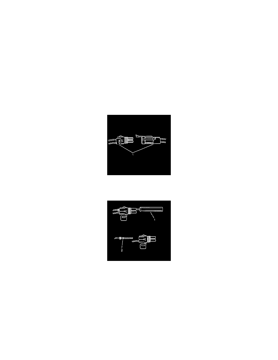
Terminal Removal Procedure
The following is the proper procedure for the repair of Weather Pack(R) Connectors.
1. Separate the connector halves (1).
2. Open the secondary lock. A secondary lock aids in terminal retention and is usually molded to the connector (1).
3. Grasp the wire and push the terminal to the forward most position. Hold the wire in this position.
4. Insert the Weather Pack(R) terminal removal tool J-38125-10A into the front (mating end) of the connector cavity until it rests on the cavity
shoulder (1).
5. Gently pull on the wire to remove the terminal through the back of the connector (2).
Note: Never use force to remove a terminal from a connector.
6. Inspect the terminal and connector for damage. Repair as necessary. Refer to Repairing Connector Terminals (Terminated Lead Repair) (See:
General Electrical Diagnostic Procedures/Connector Repairs/Repairing Connector Terminals (Terminated Lead Repair))Repairing Connector
Terminals (Terminal Repair) (See: General Electrical Diagnostic Procedures/Connector Repairs/Repairing Connector Terminals (Terminal
Repair)).
7. Reform the lock tang (2) and reset terminal in connector body.
8. Close secondary locks and join connector halves.
9. Verify that circuit is complete and working satisfactorily.
10. Perform system check.
11. Repair the terminal by following the Repairing Connector Terminals (Terminated Lead Repair) (See: General Electrical Diagnostic
Procedures/Connector Repairs/Repairing Connector Terminals (Terminated Lead Repair))Repairing Connector Terminals (Terminal Repair) (
See: General Electrical Diagnostic Procedures/Connector Repairs/Repairing Connector Terminals (Terminal Repair)) procedure.