
Sierra 3500 Denali 2WD V8-6.0L (2011)
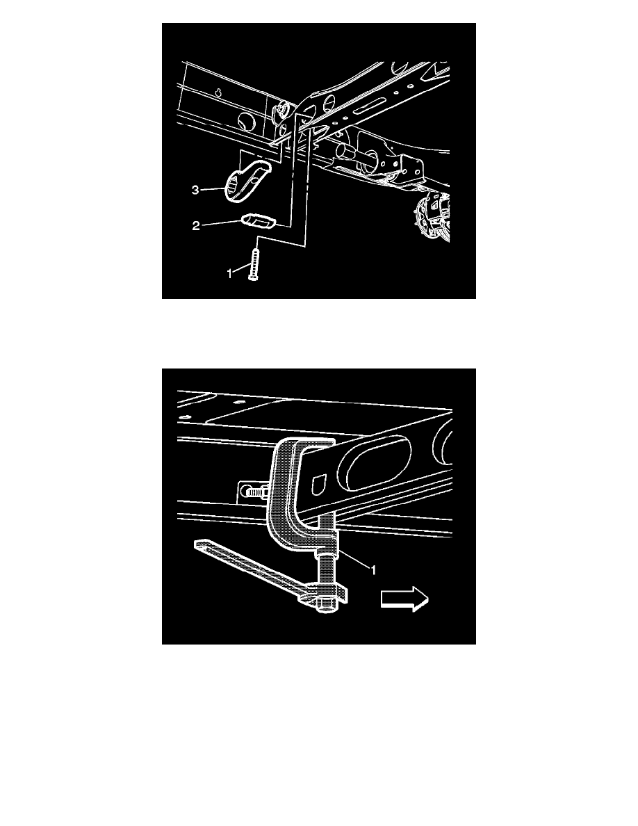
4. Install the adjustment arm (3) in the crossmember.
5. Install the adjuster nut (2) in the crossmember.
6. Install the torsion bar into the adjustment arm until the torsion bar is fully seated.
7. Install the adjuster bolt (1) until two or three turns.
8. Using the CH 48809 - tool (1), increase the tension on the adjustment arm to load the torsion bar.
Note: Refer to step (2) in the removal procedure.
9. Turn the adjuster bolt the until the length of the adjuster bolt is the same distance from the adjuster bolt head to the adjuster nut prior to removing
the bolt.
10. Remove the CH 48809 - tool (1) from the crossmember.
11. Remove the safety stands and lower the vehicle.
12. Measure the Z height. Refer to Trim Height Inspection (See: Testing and Inspection/Component Tests and General Diagnostics/Trim Height
Inspection).