
Sierra 3500 Denali 4WD V8-6.0L (2011)
the added wire.
2. Strip 5 mm (3/16 in) of insulation from the wire.
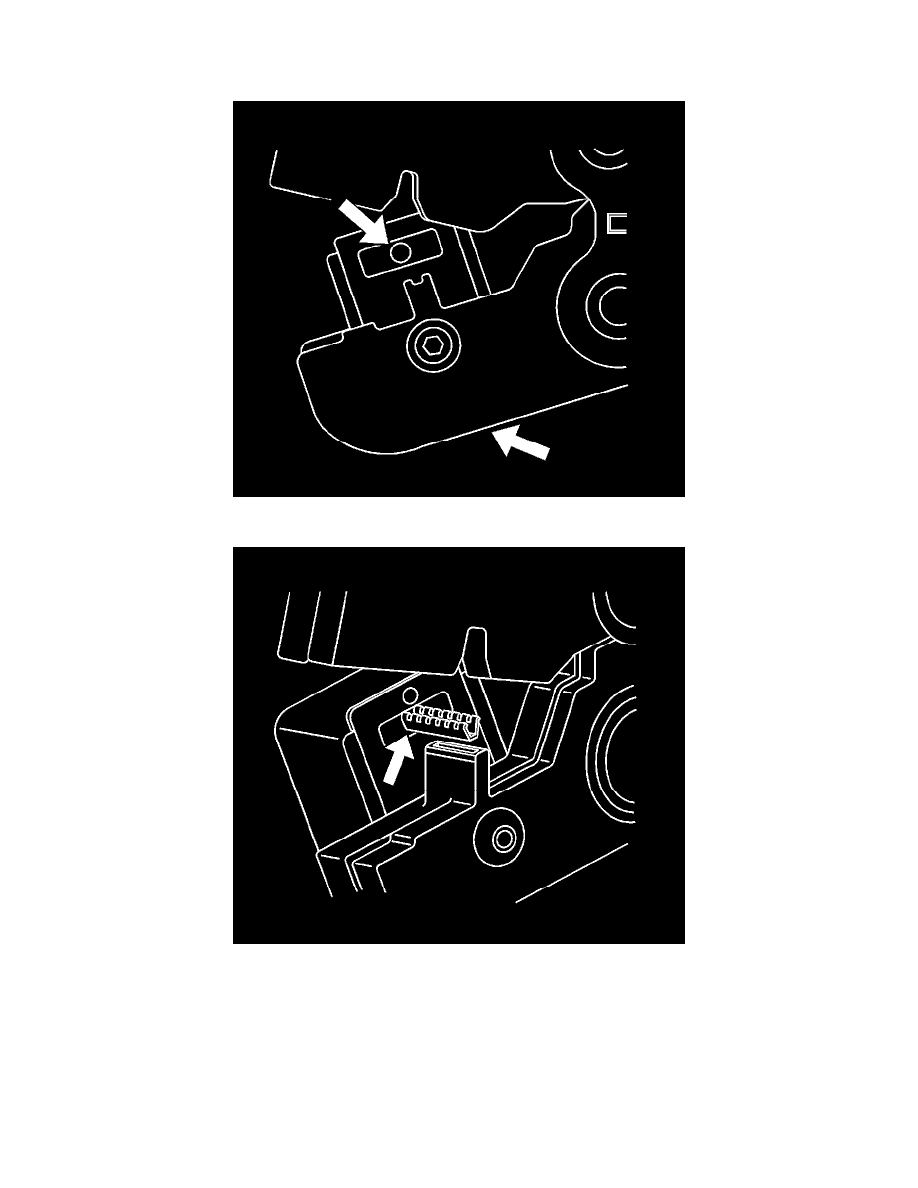
3. Depress the spring loaded locator of the J 38125-101 (W jaw) crimping tool until the terminal holder is completely visible.
4. Insert the terminal into the crimp tool until the core wings are flush with the anvil on the crimp tool. Be sure that the wings are pointed toward the
crimp tool former and release the spring locator. The locator will hold the terminal in place. Inspect the alignment of the terminal wings with the
crimp tool former. If the terminal wings are wider than the crimp tool former, remove the terminal and bend the terminal wings in slightly.
5. Place stripped wire into terminal.
6. Crimp the new terminal to the wire. If a jam occurs, press the emergency release to open applicator.
Micro 0.64 Size Terminal
The Micro 64 connectors have small terminals that are difficult to handle and hold when crimping. In order to aid the technician when crimping these
terminals, a new crimping tool was developed. The J 38125-64 (M jaw) was developed to crimp Micro 64 terminals. The J-38125-64 crimping tool has a
terminal holding block that will hold the terminal in place while the terminal is being crimped. The J-38125-64 crimping tool is also designed to crimp