
Sierra Classic 2500 4WD V8-6.0L (2007)
-
Light Blue with White Stripe: Brake switch input to power electric brake controller
-
White: ground
-
Orange: CHMSL (Center High Mounted Stop Lamp) - not required with most systems
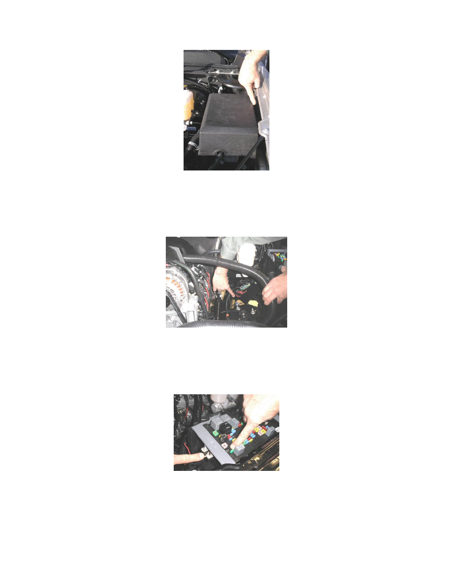
7. After completing the under dash connections to the electric brake controller, open the hood and locate the red wire that is taped to the harness
between the underhood electrical center and the driver side front fender.
8. Break the tape on the red/black wire and pull it toward the front of vehicle.
9. Remove the lid from the electrical center.
Auxiliary Power (Applies to All LD and 2007-2009 HD's Only) Without JL1
Circuit #742 for Auxiliary Power at the 7-way trailer connector is no longer connected by the GM Assembly Plant. If the customer desires auxiliary
power at the trailer connector location (i.e. refrigeration, battery charger or interior light in the trailer), complete the following steps to connect circuit
#742:
1. Locate the red/black wire, looped and taped to the chassis harness, below the brake master cylinder.
2. Break the tape and route the wire to the front of the underhood electrical center.
Important
Ensure that the ringlets are not interfering with the UBEC cover.
3. Place the terminal on the smaller of the two studs on the electrical center and secure with an M6 fastener. This is circuit #742 to stud #1 for
auxiliary power to the 7-way trailer connector.
4. ONLY for vehicles without RPO TP2 - Auxiliary Battery, install a 40 amp fuse to power the circuit.
Important
For vehicles equipped with RPO TP2 - Devices powered by this fuse will drain the vehicle battery if left connected with the vehicle not running.