
Sierra Classic 2500 4WD V8-6.0L (2007)
5. Re-form the locking device if you are going to reuse the terminal (1).
6. To repair the terminal, refer to Terminal Repair.
TERMINAL REPAIR
1. Slip the cable seal away from the terminal.
2. Cut the wire as close to the terminal as possible.
3. Slip a new cable seal onto the wire.
4. Strip 5 mm (3/16 in) of insulation from the wire.
5. Crimp a new terminal to the wire.
6. Solder the crimp with rosin core solder.
7. Slide the cable seal toward the terminal.
8. Crimp the cable seal and the insulation.
9. If the connector is outside of the passenger compartment, apply grease to the connector.
REINSTALLING TERMINAL
1. In order to reuse a terminal or lead assembly, refer to Wiring Repairs.
2. Ensure that the cable seal is kept on the terminal side of the splice.
3. Insert the lead from the back until it catches.
4. Install the TPA, CPA, and/or the secondary locks.
Delphi Connectors (Weather Pack)
DELPHI CONNECTORS (WEATHER PACK)
TOOLS REQUIRED
J-38125 Terminal Repair Kit
The following is the proper procedure for the repair of Weather Pack(R) Connectors.
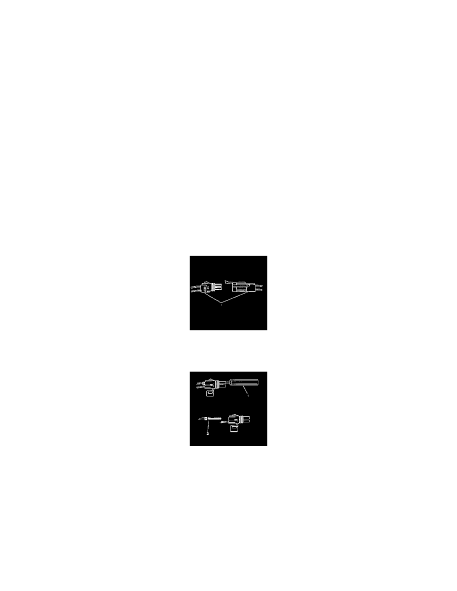
1. Separate the connector halves (1).
2. Open the secondary lock. A secondary lock aids in terminal retention and is usually molded to the connector (1).
3. Grasp the wire and push the terminal to the forward most position. Hold the wire in this position.
4. Insert the Weather Pack(R) terminal removal tool J 38125-10A (GM P/N 12014012-1) into the front (mating end) of the connector cavity until it
rests on the cavity shoulder (1).
5. Gently pull on the wire to remove the terminal through the back of the connector (2).
IMPORTANT: Never use force to remove a terminal from a connector.
6. Inspect the terminal and connector for damage. Repair as necessary.
7. Reform the lock tang (2) and reset terminal in connector body.
8. Close secondary locks and join connector halves.
9. Verify that circuit is complete and working satisfactorily.
10. Perform system check.
Delphi Connectors (12 Way)