
Sierra Denali RWD V8-6.2L (2009)
Note
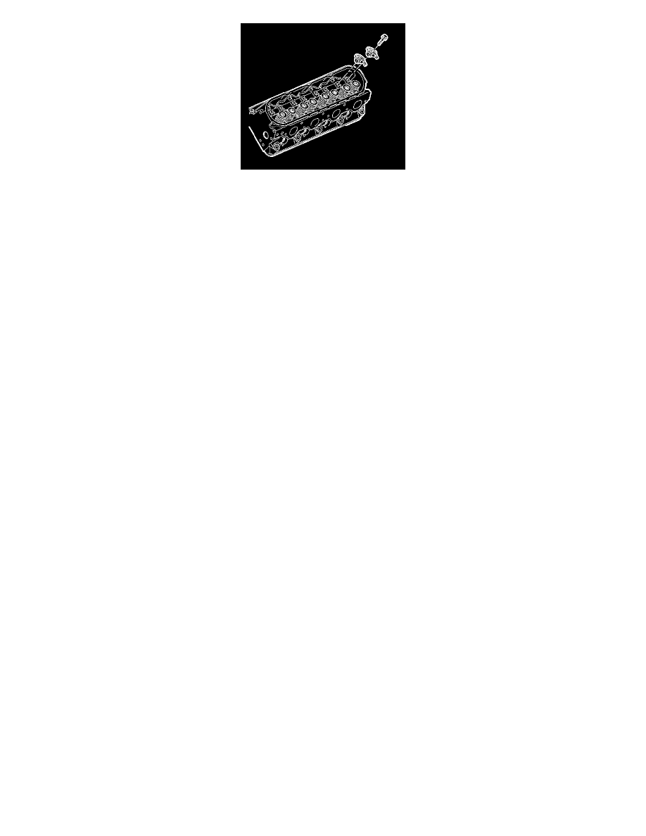
Make sure that the pushrods seat properly to the ends of the rocker arms. DO NOT tighten the rocker arm bolts at this time.
5. Install the rocker arms and bolts.
Note
The engine firing order is 1, 8, 7, 2, 6, 5, 4, 3. Cylinders 1, 3, 5 and 7 are the left bank. Cylinders 2, 4, 6 and 8 are the right bank.
6. Rotate the crankshaft until the number one piston is at top dead center (TDC) of the compression stroke. In this position, the number one cylinder
rocker arms will be off lobe lift.
Caution: Refer to Fastener Caution (See: Service Precautions/Vehicle Damage Warnings/Fastener Caution) .
7. With the engine in the number one firing position, tighten the following rocker arm bolts:
*
Tighten cylinders 1,2,7 and 8 exhaust valve rocker arm bolts to 30 Nm (22 lb ft).
*
Tighten cylinders 1,3,4 and 5 intake valve rocker arm bolts to 30 Nm (22 lb ft).
8. Rotate the crankshaft 360 degrees.
9. Tighten the following rocker arm bolts:
*
Tighten cylinders 3, 4, 5 and 6 exhaust valve rocker arm bolts to 30 Nm (22 lb ft).
*
Tighten cylinders 2, 6, 7 and 8 intake valve rocker arm bolts to 30 Nm (22 lb ft).
10. Install the number one cylinder spark plug. Refer to Spark Plug Replacement (See: Tune-up and Engine Performance Checks/Spark Plug/Service
and Repair) .
11. Install the rocker arm cover. Refer to Valve Rocker Arm Cover Replacement - Left Side (See: Valve Cover/Service and Repair/Valve Rocker
Arm Cover Replacement - Left Side) or Valve Rocker Arm Cover Replacement - Right Side (See: Valve Cover/Service and Repair/Valve Rocker
Arm Cover Replacement - Right Side) .