
Suburban 3/4 Ton 4WD V8-305 5.0L (1986)
Timing Chain: Service and Repair
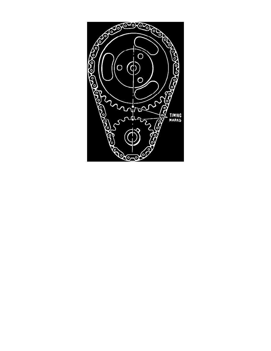
Fig. 34 Valve timing marks. V6-229, 262, V8-267, 305, 350, 400 & 454
V6-229, 262, V8-267, 305, 350, 400 & 454
1.
Remove timing case cover as outlined previously.
2.
Remove crankshaft oil slinger.
3.
Crank engine until "O" marks on sprockets are in alignment, Fig. 34.
4.
Remove three camshaft-to-sprocket bolts.
5.
Remove camshaft sprocket and timing chain together. Sprocket is a light press fit on camshaft for approximately 1/8 inch. If sprocket does not
come off easily, a light blow with a plastic hammer on the lower edge of the sprocket should dislodge it.
6.
If crankshaft sprocket is to be replaced, remove it with a suitable gear puller. Install new sprocket, aligning key and keyway.
7.
Install chain onto camshaft sprocket. Hold sprocket with chain hanging vertically, then align marks on sprockets as shown, Fig. 34. The valve
timing marks shown in Fig. 34, do not indicate TDC compression stroke for No. 1 cylinder, which is used during distributor installation.
If distributor was removed, install timing chain and sprockets, aligning timing marks, Fig. 34, then rotate engine until No. 1 cylinder is on
compression and camshaft timing mark is 180° from valve timing position shown in Fig. 34. Install distributor.
8.
Align dowel in camshaft with dowel hole in sprocket and install sprocket on camshaft. Do not attempt to drive sprocket on camshaft as welch plug
at rear of engine can be dislodged.
9.
Draw sprocket onto camshaft, using the three mounting bolts. Tighten to 20 ft. lbs. torque.
10.
Lubricate timing chain and install cover.