
Syclone V6-262 4.3L Turbo (1991)
Air Conditioning Control Assembly Fan Vacuum Positions
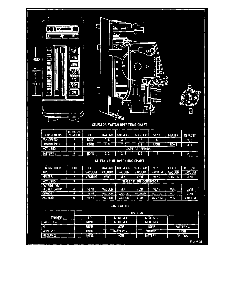
VACUUM SYSTEM
Ports on rotary vacuum valves are illustrated to provide simplicity in following vacuum schematic lines but are numbered in consecutive order on the
actual valve. (Refer to the accompanying figures).
Start the engine and allow it to idle. Move the selector lever to each position and refer to the vacuum diagrams and operational charts for airflow, air
door functioning and vacuum circuits. If airflow is not out of the proper outlet at each selector lever position do the following: