
Syclone V6-262 4.3L Turbo (1991)
Brake Light Switch: Description and Operation
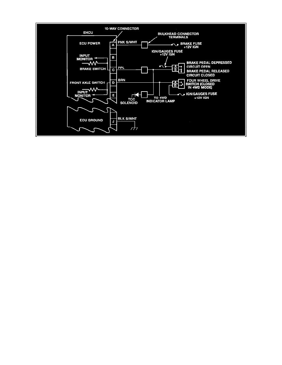
Brake And 4WD Switch Circuits
The 4WAL system uses an input signal circuit to the ECU from a brake-pedal activated switch circuit. When the driver applies the brake pedal, the
circuit voltage at ECU terminal C is zero volts. A released brake pedal will close the switch contacts, providing 12 volts at terminal C. These signals tell
the ECU:
^
Not to prepare for possible antilock braking (12 volts)
^
To get ready for control valve operation during antilock braking (low voltage)
The brake switch contacts also control power to the TCC solenoid on vehicles equipped with automatic transmissions.
The ECU will disable antilock control, complete the "Antilock" light circuit, and store a trouble code if it detects a continuous low-voltage brake switch
input (brakes applied signal) when the ignition switch has been turned to "run" and the vehicle is moving at a speed above 35 mph for 10 seconds. This
indicates that the brake switch circuit is open continuously (Code 81).
Another indication is that the ABS light will go ON when vehicle speed exceeds 15 miles-per-hour and will go OFF when vehicle speed falls below 15
miles-per-hour.