
Syclone V6-262 4.3L Turbo (1991)
1.
Clean all parts with solvent and blow dry.
2.
Inspect rotating components as follows:
a.
Vane tips for scoring or wear.
b.
Fit of vanes in rotor. Vanes must fit properly in slots without sticking or excessive play.
c.
Rotor slots for burrs and excessive wear at thrust faces.
d.
Inner surface of pump ring for scoring or wear.
e.
Thrust plate and pressure plate for wear on plate surfaces.
f.
If heavy wear is present, or parts are faulty, replace entire rotating group.
3.
Inspect bearing for rough or looseness and bearing seal for leakage, cracking or swelling.
4.
Check driveshaft and bearing bore for excessive burning or scoring.
5.
Control valve must move smoothly in the valve bore.
Assembly
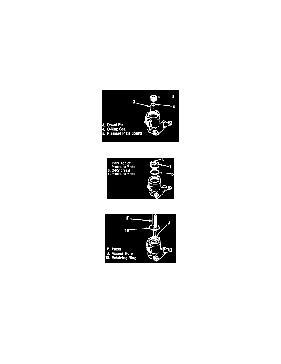
Fig. 9 Dowel pin installation
Fig. 10 Pressure Plate Alignment
Fig. 11 Thrust plate compression
1.
Press sleeve into housing using a suitable socket and press.
2.
Install dowel pin, seal and pressure plate spring. Fig. 9.
3.
Install O-ring seal, pressure plate and dowel pins. Mark top of pressure plate where pin enters from underneath to ease alignment with dowel pin
during assembly, Fig. 10.
4.
Lubricate O-ring, pump ring, rotor and vanes with power steering fluid. Install vanes and rotor with rounded edge facing away from rotor. Ensure
counterbore of rotor faces driveshaft end of housing.
5.
Install pump ring with identification marks facing up, then install O-ring seal and thrust plate. Thrust plate dimples must line up with bolt holes in
housing and plate must engage pump ring dowel pins.
6.
Using a press to compress thrust plate, install retaining plate with the center opening of ring with bolt hole nearest the access hole, Fig. 11.
7.
Using a suitable socket and press, install driveshaft seal into housing until it bottoms.