
Terrain FWD L4-2.4L (2010)
5. Press the Hz button on the DMM.
6. The DMM will display the frequency measured.
Measuring Voltage
Measuring Voltage
Special Tools
EL 39200 - Digital Multimeter (DMM)
For equivalent regional tools, refer to Special Tools (See: Tools and Equipment).
Caution: Refer to Test Probe Caution (See: Service Precautions/Vehicle Damage Warnings/Test Probe Caution).
The following procedure measures the voltage at a selected point in a circuit.
1. Disconnect the electrical harness connector for the circuit being tested, if necessary.
2. Enable the circuit and/or system being tested. Use the following methods:
*
Turn ON the ignition, with the engine OFF.
*
Turn ON the engine.
*
Turn ON the circuit and/or system with a scan tool in Output Controls.
*
Turn ON the switch for the circuit and/or system being tested.
3. Select the V (AC) or V (DC) position on the Digital Multimeter (DMM).
4. Connect the positive lead of the DMM to the point of the circuit to be tested.
5. Connect the negative lead of the DMM to a good ground.
6. The DMM displays the voltage measured at that point.
Measuring Voltage Drop
Measuring Voltage Drop
Special Tools
EL 39200 - Digital Multimeter (DMM)
For equivalent regional tools, refer to Special Tools (See: Tools and Equipment).
Caution: Refer to Test Probe Caution (See: Service Precautions/Vehicle Damage Warnings/Test Probe Caution).
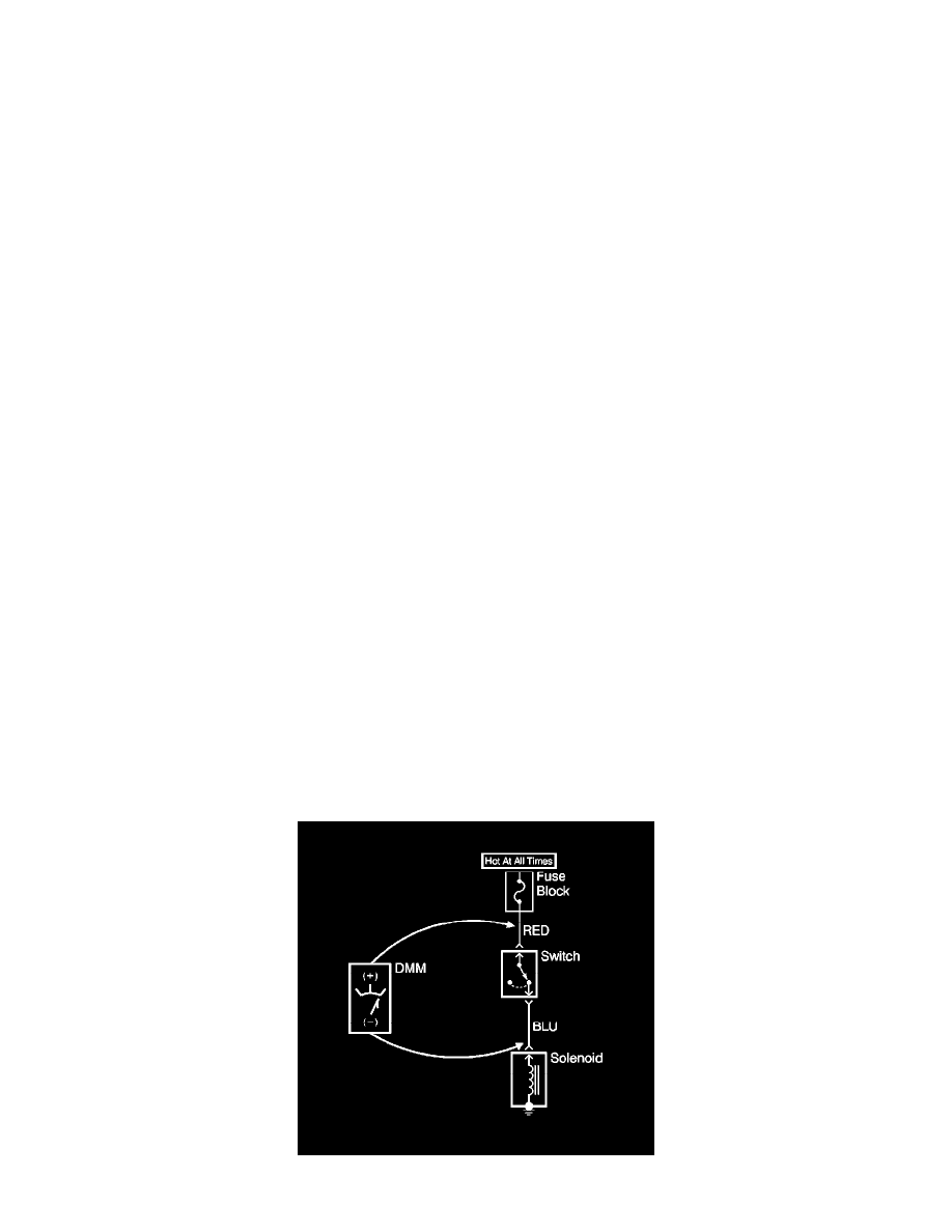
The following procedure determines the difference in voltage potential between 2 points.
1. Set the rotary dial of the Digital Multimeter (DMM) to the V (DC) position.