
Terrain FWD L4-2.4L (2010)
Procedures/Connector Repairs/Delphi Connectors (Weather Pack))Delphi Connectors (Push To Seat) (See: Testing and Inspection/Component Tests
and General Diagnostics/General Electrical Diagnostic Procedures/Connector Repairs/Delphi Connectors (Push to Seat))Delphi Connectors (Pull To
Seat) (See: Testing and Inspection/Component Tests and General Diagnostics/General Electrical Diagnostic Procedures/Connector Repairs/Delphi
Connectors (Pull to Seat))Delphi Connectors (Micro-Pack 100W) (See: Testing and Inspection/Component Tests and General Diagnostics/General
Electrical Diagnostic Procedures/Connector Repairs/Delphi Connectors (Micro-Pack 100W))Delphi Connectors (Micro.64) (See: Testing and
Inspection/Component Tests and General Diagnostics/General Electrical Diagnostic Procedures/Connector Repairs/Delphi Connectors (Micro .64)
)Delphi Connectors (12-Way) (See: Testing and Inspection/Component Tests and General Diagnostics/General Electrical Diagnostic
Procedures/Connector Repairs/Delphi Connectors (12-Way))Delphi Connectors (Steering Gear) (See: Testing and Inspection/Component Tests and
General Diagnostics/General Electrical Diagnostic Procedures/Connector Repairs/Delphi Connectors (Steering Gear))
*
The TPA and CPA should be removed before releasing the terminal for the connector body.
*
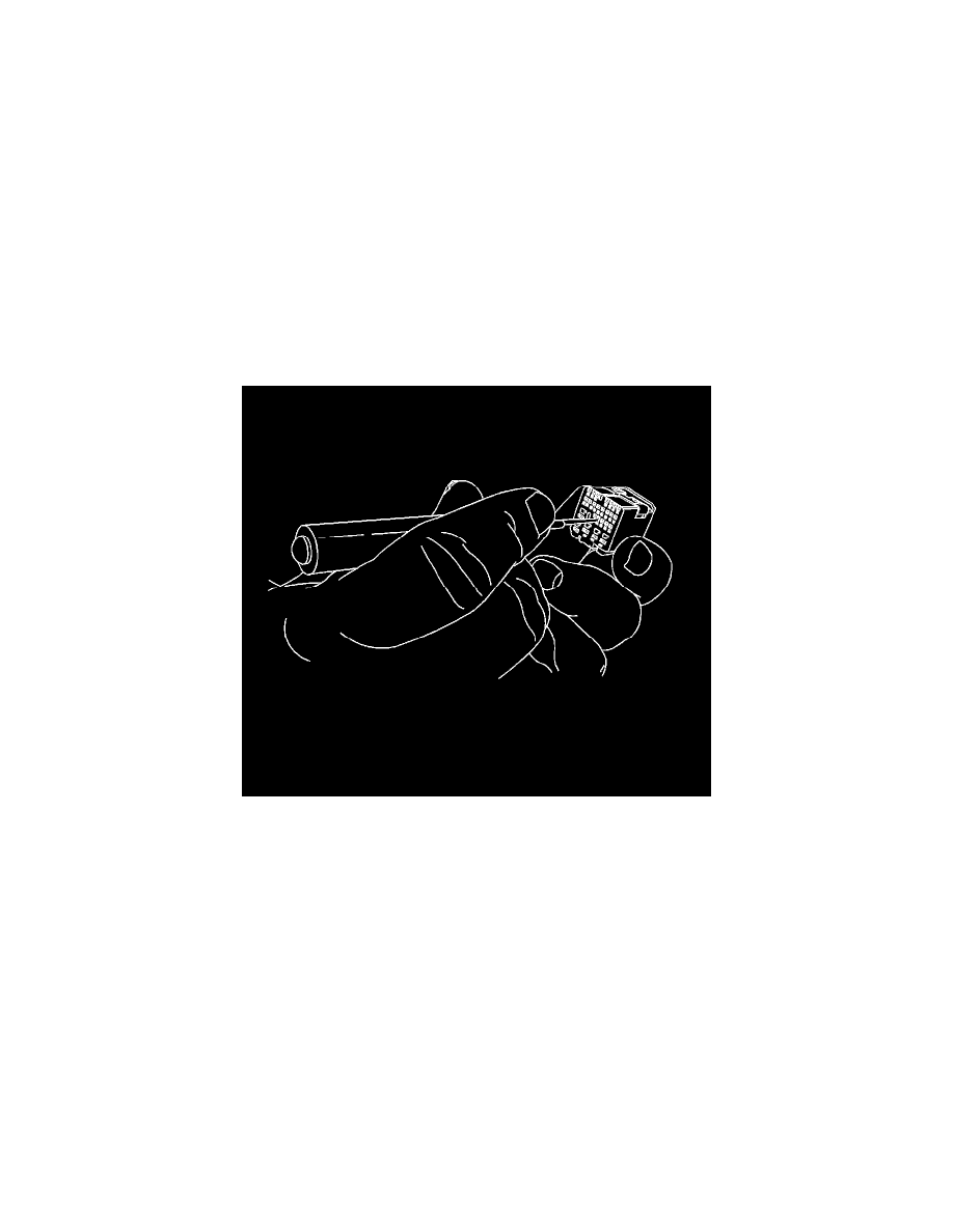
Look at the connector end view to locate the cavity of the damaged terminal and find the proper terminal release tool from the terminal release tool
kit.
Note: Using the incorrect terminal release tool can damage the connector body.
*
Insert the terminal release tool into the cavity.
Note: Some terminals have a lever that must be disengaged before the terminal can be released.
Gently pull the wire out of the back of the connector.
Terminated Lead Repair
Terminated Lead Repair
Special Tools
*
EL-38125-10 - Splice Sleeve Crimp Tool
*
EL-38125-580 - Terminal Release Tool Kit
*
J-38125-5 - Ultra Torch
*
EL-35616 - Connector Test Adapter Kit
For equivalent regional tools, refer to Special Tools (See: Power and Ground Distribution/Tools and Equipment).
Note: All repairs near the engine manifold, turbo engine and all exhaust pipes should follow the High Temperature Wiring Repairs (See: Testing and
Inspection/Component Tests and General Diagnostics/General Electrical Diagnostic Procedures/Wiring Repairs/High Temperature Wiring Repairs)
procedures.
Terminated leads are terminals that are crimped onto wires. The terminated lead can be used throughout the vehicle since it is designed for temperatures
up to 150°C. The length of the wire is 450 mm.