
V 1500 P/U 4WD V8-454 7.4L (1987)
Intake Manifold: Service and Repair
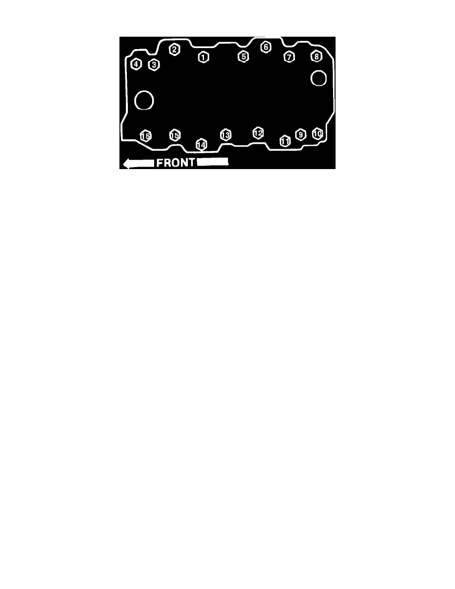
Fig. 12B Intake manifold tightening sequence. 1987 V8-454
1987
1.
Disconnect battery ground cable, then remove air cleaner assembly.
2.
Drain cooling system, then disconnect upper radiator hose and water pump bypass hose.
3.
On carbureted engines, disconnect heater hose from intake manifold.
4.
On fuel injected engines, disconnect heater hose and pipes, then the wire sensor from front if intake manifold.
5.
On all engines, disconnect accelerator cable, cruise control cable and TVS cable, as equipped.
6.
Disconnect wiring harness from clips on intake manifold, then remove cruise control transducer, if equipped.
7.
Disconnect fuel line from carburetor or fuel lines from TBI unit.
8.
Disconnect crankcase ventilation hoses and any other vacuum hoses necessary for intake manifold removal.
9.
Remove distributor assembly.
10.
On fuel injected engines, disconnect wires from ignition coil, then remove EGR solenoid and MAP sensor with brackets.
11.
On models equipped with A/C, remove A/C compressor rear bracket.
12.
On models equipped with fuel injected engine, remove front alternator/AIR pump bracket.
13.
On models equipped with carbureted engine, remove upper alternator bracket.
14.
On all models, remove intake manifold attaching bolts and the manifold.
15.
Reverse procedure to install, using new gaskets and seals. Torque manifold attaching bolts to specification in sequence shown in Fig. 12B.