
V 2500 P/U 4WD V8-350 5.7L (1987)
Air/Fuel Mixture: Adjustments
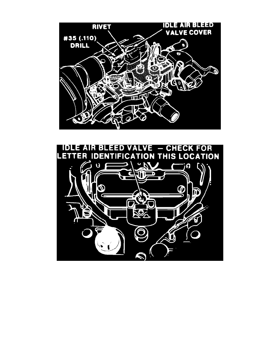
Fig. 5 Idle air bleed valve cover removal
Fig. 6 Idle air bleed valve identification
1.
Connect dwell meter to test lead in MC solenoid harness (usually a green wire) and set meter on 6 cylinder scale. Connect tachometer to engine
following manufacturer's instructions.
2.
Disconnect and plug vacuum hoses as directed by underhood vehicle emissions label.
3.
Start engine and run until it reaches normal operating temperature and dwell reading begins to fluctuate. Adjustments must be made with C3
system operating in ``Closed Loop'' mode, indicated by a fluctuating dwell reading. It is essential that coolant temperature and oxygen sensors be
at operating temperature during adjustments. Some engines may enter ``Open Loop'' mode at idle (indicated by fixed dwell reading), due to
cooling of oxygen sensor. In this case, place transmission in neutral and run engine at fast idle until dwell reading begins to fluctuate.
4.
Place transmission in Drive (manual transmission in Neutral) and check curb idle speed. If curb idle speed is not within specifications on models
equipped with Idle Speed Control (ISC) refer to ``Idle Speed Control (ISC) Adjustment'' for adjustment procedure.
5.
With engine at specified curb idle speed, dwell meter should indicate a fluctuating reading with a 10°-50° range.
6.
If dwell reading is within specifications, mixture adjustment is correct.
7.
If dwell reading is not within specifications, remove cover from idle air bleed valve, Fig. 5:
a. Stop engine and cover carburetor air intake, vents, etc. to prevent metal chips from entering engine.